Variant Elements Within Buses
This example explains how to create buses with elements having different variant conditions.
Explore the Model
Open the slexVariantBus model.
open_system("slexVariantBus")
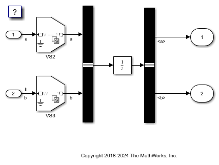
The model consists of two signals, a and b, which are merged to form a bus. These signals have variant conditions, V == 1 and W == 1 respectively. During simulation, the bus selector receives two signals with different variant conditions V == 1 and W == 1.
sim("slexVariantBus")
ans =

  Simulink.SimulationOutput:

     SimulationMetadata: [1x1 Simulink.SimulationMetadata]
           ErrorMessage: [0x0 char]
When you select individual signals from the bus using the bus selector, the corresponding variant condition is also selected. There is no difference in the propagation behavior of variant conditions when passing through virtual or nonvirtual buses. For more information on buses, see Explore Simulink Bus Capabilities.
Generate Code for Variant Buses
A virtual bus does not appear as a structure or any other coherent unit in the generated code. A separate copy of any algorithm that manipulates the bus exists for each bus element. Whereas, a nonvirtual bus appears as a structure in the generated code, and only one copy exists of any algorithm that uses the bus. The use of a structure in the generated code can be helpful when tracing the correspondence between the model and the code. For more information, see Generate Code for Variant Elements Within Buses (Simulink Coder).
Variant Bus with Model Block
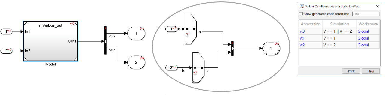
Consider this model containing a Model block.
This model has two signals a and b which have different variant conditions, V == 1 and V == 2. The Model block feeds the bus selector two signals having two different variant conditions (V == 1 and V == 2). During simulation, the Model block propagates the variant conditions received from the referenced model mVarBus_bot at its output ports. The variant condition at each output port is the logical OR of the variant conditions V == 1 and V == 2 from the variant choices of the mVarBus_bot model. For more information on variant condition propagation with Model blocks, see Propagate Variant Conditions to Enable or Disable Model or Subsystem References in Hierarchy.
Known Limitations
States logging of blocks (for example, Unit Delay) that accept buses with inactive elements is not supported.
See Also
Propagate Variant Conditions to Define Variant Regions with Variant Blocks
You can also select a web site from the following list:
Americas
- América Latina (Español)
- Canada (English)
- United States (English)
Europe
- Belgium (English)
- Denmark (English)
- Deutschland (Deutsch)
- España (Español)
- Finland (English)
- France (Français)
- Ireland (English)
- Italia (Italiano)
- Luxembourg (English)
- Netherlands (English)
- Norway (English)
- Österreich (Deutsch)
- Portugal (English)
- Sweden (English)
- Switzerland
- United Kingdom (English)