Simple Gas Model
In this example, you create a simple open-loop gas model. The model consists of a local restriction between two reservoirs. The local restriction represents a valve or an orifice. The reservoir blocks set up the boundary conditions for the local restriction.
Reservoir blocks are useful for setting up pressure and temperature boundary conditions. If you want the pressure and temperature boundary conditions to change over time, use controlled reservoir blocks.
To open the completed model, in the MATLAB® Command Window,
type ssc_gas_tutorial_step1.
To create this model:
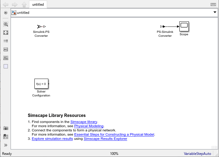
In the MATLAB Command Window, type:
sscnew
Note
By default, Simulink® Editor hides the automatic block names in model diagrams. To display hidden block names for training purposes, clear the Hide Automatic Block Names check box. For more information, see Configure Model Element Names and Labels.
Delete the Simulink-PS Converter block.
To reduce diagram clutter, click the PS-Simulink Converter block and, in the model toolstrip, select Simscape Block > Auto Name > Name Off.
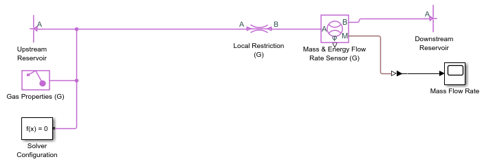
Add the following blocks.
Block Name Library Quantity Local Restriction (G) Gas/Elements 1 Reservoir (G) Gas/Elements 2 Gas Properties (G) Gas/Utilities 1 Flow Rate Sensor (G) Gas/Sensors 1 Change the reservoir block names and connect the blocks as shown in the diagram.
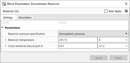
Leave the Downstream Reservoir block at standard atmospheric conditions.
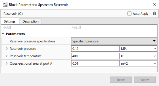
Change the Upstream Reservoir block to have a specified pressure of 0.12 MPa and temperature of 400 K.
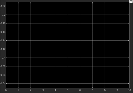
Simulate the model. The mass flow rate through the restriction is approximately 0.13 kg/s.