Power Amplifier and DPD Modeling for Dynamic EVM Measurement
This example shows how to use input and output modulated waveforms to extract a generalized memory polynomial model of a power amplifier (PA). You can use a PA model to measure the dynamic error vector magnitude (EVM) of the PA using a standard-compliant 5G NR test model waveform, as defined in TS 38.141-1. You can also measure the EVM in different operating conditions using digital predistortion (DPD).
The waveforms used in this example have been measured using Rohde & Schwarz instruments R&S®SMW200A and R&S®FSW. For more information, see Linearization of RF Amplifiers: Connecting simulation and measurements on physical devices.
This example guides you step by step through all the operations required to extract a PA model using measured data, verify the quality of the fitted model, and simulate such model using RF Blockset™ Circuit Envelope blocks with and without DPD.
To obtain a generalized memory polynomial model of PA and subsequently utilize this model for dynamic EVM measurement using DPD, four steps need to be followed. These steps are outlined below:
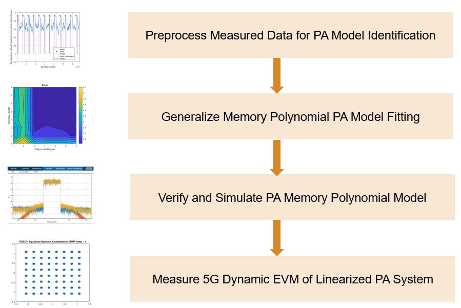
Part 1: Preprocess Measured Data for PA Model Identification
In this part, you:
Import the PA characterization data. This example uses two different input/output complex modulated waveforms measured in different conditions to extract and verify the quality of the PA model.
Visualize the characterization data in different domains , so that you can use the data to fit a memory polynomial PA model.
Manipulate the PA measured data by adjusting the input/output timing alignment. In this example, you filter the data to reduce the characterization bandwidth.
Evaluate different data processing techniques to compensate for undesired effects impacting the measured data such as frequency, phase, and DC offsets.
For more information, see Preprocess Measured Data for PA Model Identification.
Part 2: Generalize memory polynomial PA model fitting
In this part, you:
Identify the PA model coefficients matrix using the characterization waveform with the largest dynamic range, and then verify the quality of the fitted model using the other waveforms.
Experiment by changing the harmonic order and memory depth of the model. Use grid-search algorithms for optimal model identification.
For more information, see Generalize Memory Polynomial Power Amplifier Model Fitting.
Part 3: Verify and Simulate PA memory polynomial model
In this part, you:
Define a simple RF Blockset circuit envelope testbench to verify that the extracted PA model is correctly configured for time domain simulation. This step is necessary to make sure that the simulation setup uses the desired port definition and time step.
Explore the validity of the model for input signals with a different power level and bandwidth.
For more information, see PA Memory Polynomial Model Simulation and Verification.
Part 4: Measure 5G dynamic EVM of linearized PA system
In this part, you:
Define a 5G Toolbox™ testbench to generate "standard-compliant 5G waveform and measure the EVM and then integrate the RF Blockset circuit envelope model of the PA into the testbench using the
rfsystemworkflow.Run the 5G EVM testbench with and without the DPD algorithm in a loop and visualize results.
For more information, see 5G Dynamic EVM Measurement of Linearized PA System.
References
[1] Morgan, Dennis R., Zhengxiang Ma, Jaehyeong Kim, Michael G. Zierdt, and John Pastalan. "A Generalized Memory Polynomial Model for Digital Predistortion of Power Amplifiers." IEEE Transactions on Signal Processing 54, no. 10 (October 2006): 3852–60. https://doi.org/10.1109/TSP.2006.879264.
[2] Gan, Li, and Emad Abd-Elrady. "Digital Predistortion of Memory Polynomial Systems Using Direct and Indirect Learning Architectures." In Proceedings of the Eleventh IASTED International Conference on Signal and Image Processing (SIP) ed. F. Cruz-Roldán and N. B. Smith, No. 654-802. Calgary, AB: ACTA Press, 2009.
[3] Lörner Markus, Florian Ramian, and Giorgia Zucchelli. "Linearization of RF amplifiers." Application note. Version 1e.09.2021. https://www.rohde-schwarz.com/us/applications/linearization-of-rf-amplifiers-application-note_56280-1110210.html.
[4] 3GPP TS 38.141-1. "NR; Base Station (BS) conformance testing Part 1: Conducted conformance testing." 3rd Generation Partnership Project; Technical Specification Group Radio Access Network.