4-Way 3-Position Directional Valve (IL)

Libraries:
Simscape /
Fluids /
Isothermal Liquid /
Valves & Orifices /
Directional Control Valves
Description
The 4-Way 3-Position Directional Valve (IL) block models a valve with four openings in an isothermal liquid network, typically between an actuator, pump, and tank. The valve operation is controlled by a single spool displaced according to the signal at port S. You can set the baseline configuration of your valve by specifying the orifices that are open when the spool is in the neutral position (centered at 0 m) in the Neutral spool position open connections parameter, when the spool moves in the positive direction in the Positive spool position open connections parameter, and when the spool moves in the negative direction in the Negative spool position open connections.
You can set the model for valve opening in the Orifice parameterization parameter as a linear relationship or function of user-provided data, which can be applied to one or all flow paths in the valve.
Example Valve Setup

In this example configuration, Neutral spool position open
connections is set to All closed. When the
spool is in the neutral position, all orifices are closed to flow:

In this configuration, Negative spool position open connections
is set to P-A and B-T. When the signal at port
S moves the spool to a negative position, the paths between
ports P and A and between ports
B and T are open to flow. The paths
between ports P and B and ports
A and T are closed to flow:

In this configuration, Positive spool position open connections
is set to P-B and A-T. When the signal at port
S moves the spool to a positive position, the paths between
ports P and B and between ports
A and T are open to flow and the paths
between ports P and A and between ports
B and T are closed:

Schematically, this configuration is shown as:

The left-hand side corresponds to the positive position and the right-hand side corresponds to the negative position.
Spool Displacement and Valve Configuration
The spool stroke is the amount of spool travel an orifice takes to fully open from a closed position and is defined for each orifice selected on the Valve Configuration tab. The table below shows how the stroke is calculated in accordance with the valve orifice parameterization and flow path characteristics.
Spool Stroke Based on Parameterization and Flow Path
| Orifice Parameterization | Identical for All Flow Paths | Different for Each Flow Path |
|---|---|---|
| Linear - Area vs. spool travel | Defined by the Spool travel between closed and open orifice parameter | Defined by the Spool travel between closed and open orifice parameter, for each orifice |
| Tabulated data - Area vs. spool travel | The difference between the first and last element of the Spool travel vector parameter | The difference between the first and last element of the spool travel vector parameter for each orifice |
| Tabulated data - Volumetric flow rate vs. spool travel and pressure drop | The difference between the first and last element of the Spool travel vector, ds parameter | The difference between the first and last element of the spool travel vector, ds parameter for each orifice |
The section Visualize Orifice Openings details how to see the orientation of all valve orifices.
The direction of spool movement signaled at port S depends on the spool stroke and the orifice orientation:
Orifice Definition and Spool Travel Direction
| Spool Position when Orifice is Open | Spool Travel, ΔS |
|---|---|
| Always closed (orifice is not selected in any spool position configuration) | N/A |
| Always open (orifice is selected in positive, neutral, and negative spool position configurations) | N/A |
| Negative | Sorifice_max + spool stroke – S |
| Negative and Neutral | Sorifice_max + spool stroke – S |
| Positive | Sorifice_max – spool stroke + S |
| Positive and Neutral | Sorifice_max – spool stroke + S |
| Neutral | |Sorifice_max| + spool stroke – |S| |
| Positive and Negative | –|Sorifice_max| + spool stroke – |S| |
Where Sorifice_max is the spool position at the maximum orifice area defined for each orifice. The orifice area saturates at the leakage area when ΔS is negative and saturates at the maximum orifice area when the orifice is fully open. When the orifice is fully open, ΔS is equal to the spool stroke, so ΔS greater than the spool stroke does not further increase the orifice area.
The Consistency check for neutral spool position open connections parameter verifies that
Any orifice listed in Neutral spool position open connections is open when the signal at S is 0.
Any orifice that is not listed in Neutral spool position open connections is closed when the signal at S is 0.
You can optionally choose to receive a warning or error when this check is violated.
The possible configurations of the 4-Way 3-Position Directional Valve (IL) block are shown below.
4-Way 3-Position Directional Valve Configuration
| Configuration | Parameter Values |
|---|---|
| All four orifices are closed in the neutral position. (default)
|
| All four orifices are open in the neutral position.
|
| Orifices A-T and B-T are closed. Orifices P-A and P-B are overlapped.
|
| Orifices A-T and B-T are open. Orifices P-A and P-B are overlapped.
|
| Orifices P-A and A-T are open in the neutral position. Orifices P-B and B-T are overlapped.
|
| Orifice A-T is open in the neutral position. Orifices P-B, A-T, and B-T are overlapped.
|
| Orifice B-T is open in the neutral position. Orifices P-A, P-B, and A-T are overlapped.
|
| Orifices P-A and P-B are open. Orifices A-T and B-T are overlapped.
|
| Orifice P-A is open in the neutral position. Orifices P-B, A-T, and B-T are overlapped.
|
| Orifice P-B is open in the neutral position. Orifices P-A, A-T, and B-T are overlapped.
|
| Orifices P-B and B-T are open in the neutral position. Orifices P-A and A-T are overlapped.
|
| Orifices P-A, P-B, A-T, and B-T are closed in the neutral position. P-T is open in the neutral position and closes when the spool displaces.
|
| Orifice P-A is a constant orifice. Orifices P-B, A-T, and B-T are open in the neutral position.
|
| Orifice P-B is a constant orifice. Orifices P-A, A-T and B-T are open in the neutral position.
|
| Orifice P-A is closed in the neutral position. Ports A and T do not form a flow path.
|
| Orifice P-B is closed in the neutral position. Ports B and T do not form a flow path.
|
| Orifice P-A is closed in the neutral position. Orifice A-T is open in the neutral position.
|
| Orifice P-B is closed in the neutral position. Orifice B-T is open in the neutral position.
|
| Orifice P-B is closed in the neutral position. Orifice P-T is open in the neutral position. Ports A and T do not form a flow path.
|
| Orifice P-A is closed in the neutral position. Orifice P-T is open in the neutral position. Ports A and T do not form a flow path.
|


Valve Orifice Parameterizations
The Orifice parameterization parameter sets the model for the
open area or volumetric flow rate through one or all of the valve orifices. The
block applies the same data for all flow paths if Area
characteristics is set to Identical for all flow
paths; otherwise, individual parameterizations are applied for the
Different for all flow paths setting. You can model
valve opening in three ways:
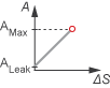
Linear - area vs. spool travelThe opening area is a linear function of the spool position received as a signal at port S:
where:
ΔS is the spool travel defined in Orifice Definition and Spool Travel Direction.
ΔSmax is the Spool travel between closed and open orifice.
Amax is the Maximum orifice area.
Aleak is the Leakage area.
Aorifice saturates at Aleak when ΔS is negative and saturates at Amax when the orifice is fully open. When the orifice is fully open, ΔS is equal to the spool stroke, so ΔS greater than the spool stroke does not further increase the orifice area.
When the valve is in a near-open or near-closed position in the linear parameterization, you can maintain numerical robustness in your simulation by adjusting the Smoothing factor parameter. If the Smoothing factor parameter is nonzero, the block smoothly saturates the opening area between Aleak and Amax. For more information, see Numerical Smoothing.
Tabulated data - Area vs. spool travelProvide spool travel vectors for your system or for individual flow paths between ports P, A, B, and T. This data will be used to calculate the relationship between the orifice area and spool displacement. Interpolation is used to determine the opening area between given data points. Aleak and Amax are the first and last parameters of the opening area vector, respectively.

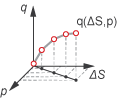
Tabulated data - Volumetric flow rate vs. spool travel and pressure dropProvide spool travel and pressure drop vectors and a dependent, 2-D volumetric flow rate array. Interpolation is used to determine flow rate between given data points. The mass flow rate is the product of the volumetric flow rate and the local density.
Visualize Orifice Openings
To visualize spool offsets and maximum displacement, right-click the block and select Fluids > Plot Valve Characteristics. The plot shows the orifices selected in the Valve Configuration settings. The orifice parameterization sets the axes, which are either:
Orifice area versus spool position
Volumetric flow rate versus spool position, queried at a specific pressure differential
When the positive, neutral, and negative settings in the Valve Configuration feature the same orifice, the plot displays the orifice openings as a constant.
To update the data after changing the block parameters, click Reload Data on the figure window.
This image shows an example valve configuration. In the Valve Configuration settings:
Positive spool position open connections is
P-A and B-T.Neutral spool position open connections is
P-T only.Negative spool position open connections is
P-B and A-T.
In the P-A Orifice settings:
Spool position at maximum P-A orifice area is
2.5e-3 m.
All other spool positions are at the default values.
Example Spool Position Visualization

The visualization shows that the P-A orifice is open between the spool position at
-2.53e-3 and 2.53e-3 m. Because the P-A
orifice is open only when the spool is displaced in the positive direction, setting
the Consistency check for neutral spool and position open
connections parameter to Warning
returns:
Warning: P-A orifice must be closed when the spool is in
the neutral position. Adjust Spool position at maximum P-A orifice area, Neutral
spool position open connections, or Consistency check for neutral spool position
open connections. Right-click on the block and select Fluids > Plot Valve
Characteristics to view the area or flow of each connection versus spool
position.
To resolve this warning, you can change:
Spool position at maximum P-A orifice area to a value larger than 0.005 m.
Consistency check for neutral spool position open connections to
None.The valve configuration by setting Neutral spool position open connections to
P-A only.
Faults
To model a fault, in the Faults section, click the Add fault hyperlink next to the fault that you want to model. In the Add Fault window, specify the fault properties. For more information about fault modeling, see Introduction to Simscape Faults.
The Spool position when faulted parameter has four fault options:
Positive— The spool position freezes in the positive position, opening the flow paths specified by the Positive spool position open connections parameter to their maximum value. The flow paths specified by the Negative spool position open connections and Neutral spool position open connections parameters are closed.Neutral— The spool position freezes in the neutral position, opening all flow paths to their specified values at 0 m.Negative— The spool position freezes in the negative position, opening the flow paths specified by the Negative spool position open connections parameter to their maximum value. The flow paths specified by the Positive spool position open connections and Neutral spool position open connections parameters are closed.Maintain last value— The valve freezes at the spool position when the trigger occurs.
Due to numerical smoothing at the extremes of the valve area, in the linear parameterization, the minimum area that he block uses is larger than the Leakage area, and the maximum is smaller than the Maximum orifice area, in proportion to the Smoothing factor value. For more information, see Numerical Smoothing.
After the fault triggers, the valve remains at the faulted area for the rest of the simulation.
Composite Structure
This block is a composite component comprising of multiple instances of the Orifice (IL) block. Refer to the Orifice (IL) block for more detail on the valve parameterizations and block calculations.
Predefined Parameterization
You can populate the block with pre-parameterized manufacturing data, which allows you to model a specific supplier component.
To load a predefined parameterization:
In the block dialog box, next to Selected part, click the "<click to select>" hyperlink next to Selected part in the block dialogue box settings.
The Block Parameterization Manager window opens. Select a part from the menu and click Apply all. You can narrow the choices using the Manufacturer drop down menu.
You can close the Block Parameterization Manager menu. The block now has the parameterization that you specified.
You can compare current parameter settings with a specific supplier component in the Block Parameterization Manager window by selecting a part and viewing the data in the Compare selected part with block section.
Note
Predefined block parameterizations use available data sources to supply parameter values. The block substitutes engineering judgement and simplifying assumptions for missing data. As a result, expect some deviation between simulated and actual physical behavior. To ensure accuracy, validate the simulated behavior against experimental data and refine your component models as necessary.
To learn more, see List of Pre-Parameterized Components.
Examples


Ports
Conserving
Input
Parameters
Extended Capabilities
Version History
Introduced in R2020aYou can also select a web site from the following list:
Americas
- América Latina (Español)
- Canada (English)
- United States (English)
Europe
- Belgium (English)
- Denmark (English)
- Deutschland (Deutsch)
- España (Español)
- Finland (English)
- France (Français)
- Ireland (English)
- Italia (Italiano)
- Luxembourg (English)
- Netherlands (English)
- Norway (English)
- Österreich (Deutsch)
- Portugal (English)
- Sweden (English)
- Switzerland
- United Kingdom (English)