Main Content

patternElevation

Plot antenna or transducer element directivity and pattern versus elevation

Since R2019a

Description

patternElevation(element,FREQ) plots the 2-D element directivity pattern versus elevation (in dBi) for the element element at zero-degrees azimuth angle. The argument FREQ specifies the operating frequency.

patternElevation(element,FREQ,AZ), in addition, plots the 2-D element directivity pattern versus elevation (in dBi) at the azimuth angle specified by AZ. When AZ is a vector, multiple overlaid plots are created.

patternElevation(element,FREQ,AZ,Name,Value) plots the element pattern with additional options specified by one or more Name,Value pair arguments.

PAT = patternElevation(___) returns the element pattern. PAT is a matrix whose entries represent the pattern at corresponding sampling points specified by the 'Elevation' parameter and the AZ input argument.

Input Arguments

collapse all

Antenna or transducer element, specified as a Phased Array System Toolbox System object.

Frequency for computing directivity and pattern, specified as a positive scalar. Frequency units are in hertz.

  • For an antenna or microphone element, FREQ must lie within the range of values specified by the FrequencyRange or the FrequencyVector property of the element. Otherwise, the element produces no response and the directivity is returned as –Inf. Most elements use the FrequencyRange property except for phased.CustomAntennaElement and phased.CustomMicrophoneElement, which use the FrequencyVector property.

  • For an array of elements, FREQ must lie within the frequency range of the elements that make up the array. Otherwise, the array produces no response and the directivity is returned as –Inf.

Example: 1e8

Data Types: double

Azimuth angles for computing sensor or array directivities and patterns, specified as a 1-by-N real-valued row vector where N is the number of desired azimuth directions. Angle units are in degrees. The azimuth angle must lie between –180° and 180°.

The azimuth angle is the angle between the x-axis and the projection of the direction vector onto the xy plane. This angle is positive when measured from the x-axis toward the y-axis.

Example: [0,10,20]

Data Types: double

Name-Value Arguments

Specify optional pairs of arguments as Name1=Value1,...,NameN=ValueN, where Name is the argument name and Value is the corresponding value. Name-value arguments must appear after other arguments, but the order of the pairs does not matter.

Before R2021a, use commas to separate each name and value, and enclose Name in quotes.

Example: Azimuth,[-90:90],Type,'directivity'

Displayed pattern type, specified as the comma-separated pair consisting of 'Type' and one of

  • 'directivity' — directivity pattern measured in dBi.

  • 'efield' — field pattern of the sensor or array. For acoustic sensors, the displayed pattern is for the scalar sound field.

  • 'power' — power pattern of the sensor or array defined as the square of the field pattern.

  • 'powerdb' — power pattern converted to dB.

Example: 'powerdb'

Data Types: char

Elevation angles, specified as the comma-separated pair consisting of 'Elevation' and a 1-by-P real-valued row vector. Elevation angles define where the array pattern is calculated.

Example: 'Elevation',[-90:2:90]

Data Types: double

Output Arguments

collapse all

Element directivity or pattern, returned as an P-by-N real-valued matrix. The dimension P is the number of elevation angles determined by the 'Elevation' name-value pair argument. The dimension N is the number of azimuth angles determined by the AZ argument.

More About

collapse all

Directivity

Directivity describes the directionality of the radiation pattern of a sensor element or array of sensor elements.

Higher directivity is desired when you want to transmit more radiation in a specific direction. Directivity is the ratio of the transmitted radiant intensity in a specified direction to the radiant intensity transmitted by an isotropic radiator with the same total transmitted power

D=4πUrad(θ,φ)Ptotal

where Urad(θ,φ) is the radiant intensity of a transmitter in the direction (θ,φ) and Ptotal is the total power transmitted by an isotropic radiator. For a receiving element or array, directivity measures the sensitivity toward radiation arriving from a specific direction. The principle of reciprocity shows that the directivity of an element or array used for reception equals the directivity of the same element or array used for transmission. When converted to decibels, the directivity is denoted as dBi. For information on directivity, read the notes on Element Directivity and Array Directivity.

Azimuth and Elevation Angles

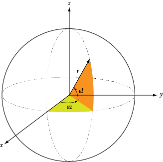
The azimuth angle of a vector is the angle between the x-axis and its orthogonal projection onto the xy-plane. The angle is positive when going from the x-axis toward the y-axis. Azimuth angles lie between –180° and 180° degrees, inclusive. The elevation angle is the angle between the vector and its orthogonal projection onto the xy-plane. The angle is positive when going toward the positive z-axis from the xy-plane. Elevation angles lie between –90° and 90° degrees, inclusive.

Version History

Introduced in R2019a