hyperbolic
(Not recommended) Solve hyperbolic PDE problem
hyperbolic is not recommended. Use solvepde instead.
Syntax
Description
Hyperbolic equation solver
Solves PDE problems of the type
on a 2-D or 3-D region Ω, or the system PDE problem
The variables c, a, f, and d can depend on position, time, and the solution u and its gradient.
u = hyperbolic(u0,ut0,tlist,model,c,a,f,d)
on a 2-D or 3-D region Ω, or the system PDE problem
with geometry, mesh, and boundary conditions specified in
model, with initial value u0 and initial
derivative with respect to time ut0. The variables
c, a, f, and
d in the equation correspond to the function coefficients
c, a, f, and
d respectively.
u = hyperbolic(___,'Stats','off')
Examples
Solve the wave equation
on the square domain specified by squareg.
Create a PDE model and import the geometry.
model = createpde;
geometryFromEdges(model,@squareg);
pdegplot(model,'EdgeLabels','on')
ylim([-1.1,1.1])
axis equal
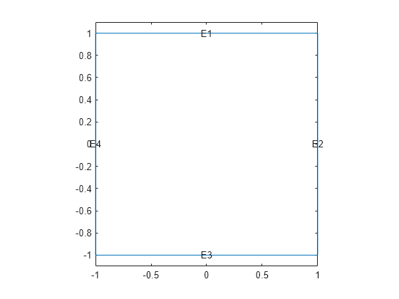
Set Dirichlet boundary conditions for , and Neumann boundary conditions
for . (The Neumann boundary condition is the default condition, so the second specification is redundant.)
applyBoundaryCondition(model,'dirichlet','Edge',[2,4],'u',0);
applyBoundaryCondition(model,'neumann','Edge',[1,3],'g',0);
Set the initial conditions.
u0 = 'atan(cos(pi/2*x))';
ut0 = '3*sin(pi*x).*exp(cos(pi*y))';
Set the solution times.
tlist = linspace(0,5,31);
Give coefficients for the problem.
c = 1;
a = 0;
f = 0;
d = 1;
Generate a mesh and solve the PDE.
generateMesh(model,'GeometricOrder','linear','Hmax',0.1);
u1 = hyperbolic(u0,ut0,tlist,model,c,a,f,d);
456 successful steps
51 failed attempts
1016 function evaluations
1 partial derivatives
134 LU decompositions
1015 solutions of linear systems
Plot the solution at the first and last times.
figure
pdeplot(model,'XYData',u1(:,1))
axis equal

figure
pdeplot(model,'XYData',u1(:,end))
axis equal
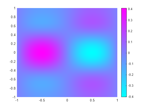
For a version of this example with animation, see Wave Equation on Square Domain.
Solve the wave equation
on the square domain specified by squareg, using a geometry function to specify the geometry, a boundary function to specify the boundary conditions, and using initmesh to create the finite element mesh.
Specify the geometry as @squareg and plot the geometry.
g = @squareg;
pdegplot(g,'EdgeLabels','on')
ylim([-1.1,1.1])
axis equal
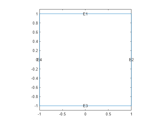
Set Dirichlet boundary conditions for , and Neumann boundary conditions
for . (The Neumann boundary condition is the default condition, so the second specification is redundant.)
The squareb3 function specifies these boundary conditions.
b = @squareb3;
Set the initial conditions.
u0 = 'atan(cos(pi/2*x))';
ut0 = '3*sin(pi*x).*exp(cos(pi*y))';
Set the solution times.
tlist = linspace(0,5,31);
Give coefficients for the problem.
c = 1;
a = 0;
f = 0;
d = 1;
Create a mesh and solve the PDE.
[p,e,t] = initmesh(g);
u = hyperbolic(u0,ut0,tlist,b,p,e,t,c,a,f,d);
462 successful steps
70 failed attempts
1066 function evaluations
1 partial derivatives
156 LU decompositions
1065 solutions of linear systems
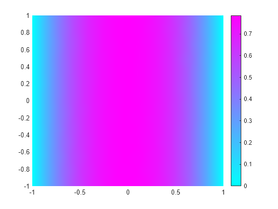
Plot the solution at the first and last times.
figure
pdeplot(p,e,t,'XYData',u(:,1))
axis equal
figure
pdeplot(p,e,t,'XYData',u(:,end))
axis equal

For a version of this example with animation, see Wave Equation on Square Domain.
Solve a hyperbolic problem using finite element matrices.
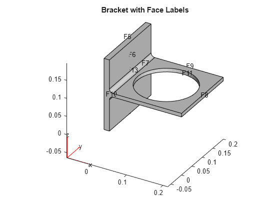
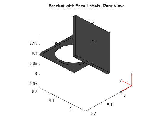
Create a model and import the BracketWithHole.stl geometry.
model = createpde();
importGeometry(model,'BracketWithHole.stl');
figure
pdegplot(model,'FaceLabels','on')
view(30,30)
title('Bracket with Face Labels')
figure
pdegplot(model,'FaceLabels','on')
view(-134,-32)
title('Bracket with Face Labels, Rear View')
Set coefficients c = 1, a = 0, f = 0.5, and d = 1.
c = 1;
a = 0;
f = 0.5;
d = 1;
Generate a mesh for the model.
generateMesh(model);
Create initial conditions and boundary conditions. The boundary condition for the rear face is Dirichlet with value 0. All other faces have the default boundary condition. The initial condition is u(0) = 0, du/dt(0) = x/2. Give the initial condition on the derivative by calculating the x-position of each node in xpts, and passing x/2.
applyBoundaryCondition(model,'Face',4,'u',0);
u0 = 0;
xpts = model.Mesh.Nodes(1,:);
ut0 = xpts(:)/2;
Create the associated finite element matrices.
[Kc,Fc,B,ud] = assempde(model,c,a,f);
[~,M,~] = assema(model,0,d,f);
Solve the PDE for times from 0 to 2.
tlist = linspace(0,5,50);
u = hyperbolic(u0,ut0,tlist,Kc,Fc,B,ud,M);
1487 successful steps
68 failed attempts
3015 function evaluations
1 partial derivatives
269 LU decompositions
3014 solutions of linear systems
View the solution at a few times. Scale all the plots to have the same color range by using the clim command.
umax = max(max(u));
umin = min(min(u));

subplot(2,2,1)
pdeplot3D(model,'ColorMapData',u(:,5))
clim([umin umax])
title('Time 1/2')
subplot(2,2,2)
pdeplot3D(model,'ColorMapData',u(:,10))
clim([umin umax])
title('Time 1')
subplot(2,2,3)
pdeplot3D(model,'ColorMapData',u(:,15))
clim([umin umax])
title('Time 3/2')
subplot(2,2,4)
pdeplot3D(model,'ColorMapData',u(:,20))
clim([umin umax])
title('Time 2')

The solution seems to have a frequency of one, because the plots at times 1/2 and 3/2 show maximum values, and those at times 1 and 2 show minimum values.
Solve a hyperbolic problem that includes damping. You must use the finite element matrix form to use damping.
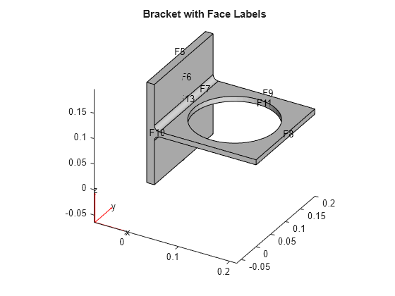
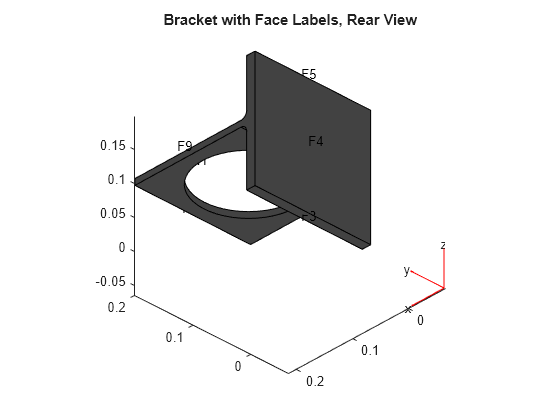
Create a model and import the BracketWithHole.stl geometry.
model = createpde();
importGeometry(model,'BracketWithHole.stl');
figure
pdegplot(model,'FaceLabels','on')
view(30,30)
title('Bracket with Face Labels')
figure
pdegplot(model,'FaceLabels','on')
view(-134,-32)
title('Bracket with Face Labels, Rear View')
Set coefficients c = 1, a = 0, f = 0.5, and d = 1.
c = 1;
a = 0;
f = 0.5;
d = 1;
Generate a mesh for the model.
generateMesh(model);
Create initial conditions and boundary conditions. The boundary condition for the rear face is Dirichlet with value 0. All other faces have the default boundary condition. The initial condition is u(0) = 0, du/dt(0) = x/2. Give the initial condition on the derivative by calculating the x-position of each node in xpts, and passing x/2.
applyBoundaryCondition(model,'Face',4,'u',0);
u0 = 0;
xpts = model.Mesh.Nodes(1,:);
ut0 = xpts(:)/2;
Create the associated finite element matrices.
[Kc,Fc,B,ud] = assempde(model,c,a,f);
[~,M,~] = assema(model,0,d,f);
Use a damping matrix that is 10% of the mass matrix.
Damping = 0.1*M;
Solve the PDE for times from 0 to 2.
tlist = linspace(0,5,50);
u = hyperbolic(u0,ut0,tlist,Kc,Fc,B,ud,M,'DampingMatrix',Damping);
1434 successful steps 67 failed attempts 2771 function evaluations 1 partial derivatives 279 LU decompositions 2770 solutions of linear systems
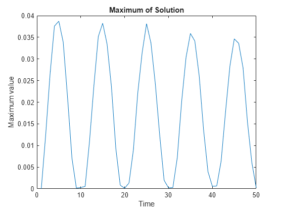
Plot the maximum value at each time. The oscillations damp slightly as time increases.
plot(max(u))
xlabel('Time')
ylabel('Maximum value')
title('Maximum of Solution')
Input Arguments
Initial condition, specified as a scalar, vector of nodal values, character vector, character
array, string scalar, or string vector. The initial condition is the value of the
solution u at the initial time, specified as a column vector of
values at the nodes. The nodes are either p in the
[p,e,t] data structure, or are
model.Mesh.Nodes.
If the initial condition is a constant scalar
v, specifyu0asv.If there are
Npnodes in the mesh, and N equations in the system of PDEs, specifyu0as a column vector ofNp*N elements, where the firstNpelements correspond to the first component of the solutionu, the secondNpelements correspond to the second component of the solutionu, etc.Give a text expression of a function, such as
'x.^2
+ 5*cos(x.*y)'
. If you have a system of N > 1 equations, give a text array such aschar('x.^2 + 5*cos(x.*y)',... 'tanh(x.*y)./(1+z.^2)')
Example: x.^2+5*cos(y.*x)
Data Types: double | char | string
Complex Number Support: Yes
Initial derivative, specified as a vector, character vector, character
array, string scalar, or string vector. The initial gradient is the value of
the derivative of the solution u at the initial time,
specified as a vector of values at the nodes. The nodes are either
p in the [p,e,t] data structure,
or are model.Mesh.Nodes.
If the initial derivative is a constant value
v, specifyu0asv.If there are
Npnodes in the mesh, and N equations in the system of PDEs, specifyut0as a vector ofNp*N elements, where the firstNpelements correspond to the first component of the solutionu, the secondNpelements correspond to the second component of the solutionu, etc.Give a text expression of a function, such as
'x.^2 +
                                    5*cos(x.*y)'
. If you have a system of N > 1 equations, use a text array such aschar('x.^2 + 5*cos(x.*y)',... 'tanh(x.*y)./(1+z.^2)')
Example: p(1,:).^2+5*cos(p(2,:).*p(1,:))
Data Types: double | char | string
Complex Number Support: Yes
Solution times, specified as a real vector. The solver returns the solution to the PDE at the solution times.
Example: 0:0.2:4
Data Types: double
PDE model, specified as a PDEModel object.
Example: model = createpde
PDE coefficient, specified as a scalar, matrix, character vector,
character array, string scalar, string vector, or coefficient function.
c represents the c coefficient in
the scalar PDE
or in the system of PDEs
Example: 'cosh(x+y.^2)'
Data Types: double | char | string | function_handle
Complex Number Support: Yes
PDE coefficient, specified as a scalar, matrix, character vector,
character array, string scalar, string vector, or coefficient function.
a represents the a coefficient in
the scalar PDE
or in the system of PDEs
Example: 2*eye(3)
Data Types: double | char | string | function_handle
Complex Number Support: Yes
PDE coefficient, specified as a scalar, matrix, character vector,
character array, string scalar, string vector, or coefficient function.
f represents the f coefficient in
the scalar PDE
or in the system of PDEs
Example: char('sin(x)';'cos(y)';'tan(z)')
Data Types: double | char | string | function_handle
Complex Number Support: Yes
PDE coefficient, specified as a scalar, matrix, character vector,
character array, string scalar, string vector, or coefficient function.
d represents the d coefficient in
the scalar PDE
or in the system of PDEs
Example: 2*eye(3)
Data Types: double | char | string | function_handle
Complex Number Support: Yes
Boundary conditions, specified as a boundary matrix or boundary file. Pass a boundary file as a function handle or as a file name. A boundary matrix is generally an export from the PDE Modeler app.
Example: b = 'circleb1', b = "circleb1", or b =
@circleb1
Data Types: double | char | string | function_handle
Mesh points, specified as a 2-by-Np matrix of points, where
Np is the number of points in the mesh. For a description of the
(p,e,t) matrices, see Mesh Data as [p,e,t] Triples.
Typically, you use the p, e, and t
data exported from the PDE Modeler app, or generated by initmesh or refinemesh.
Example: [p,e,t] = initmesh(gd)
Data Types: double
Mesh edges, specified as a 7-by-Ne matrix of edges,
where Ne is the number of edges in the mesh. For a description of the
(p,e,t) matrices, see Mesh Data as [p,e,t] Triples.
Typically, you use the p, e, and t
data exported from the PDE Modeler app, or generated by initmesh or refinemesh.
Example: [p,e,t] = initmesh(gd)
Data Types: double
Mesh triangles, specified as a 4-by-Nt matrix of
triangles, where Nt is the number of triangles in the mesh. For a
description of the (p,e,t)
matrices, see Mesh Data as [p,e,t] Triples.
Typically, you use the p, e, and t
data exported from the PDE Modeler app, or generated by initmesh or refinemesh.
Example: [p,e,t] = initmesh(gd)
Data Types: double
Stiffness matrix, specified as a sparse matrix or as a full
matrix. See Elliptic Equations. Typically, Kc is
the output of assempde.
Load vector, specified as a vector. See Elliptic Equations. Typically, Fc is the
output of assempde.
Dirichlet nullspace, returned as a sparse matrix. See Algorithms. Typically, B is
the output of assempde.
Dirichlet vector, returned as a vector. See Algorithms. Typically, ud is
the output of assempde.
Mass matrix. specified as a sparse matrix or a full matrix. See Elliptic Equations.
To obtain the input matrices for pdeeig, hyperbolic or parabolic,
run both assema and assempde:
[Kc,Fc,B,ud] = assempde(model,c,a,f);
[~,M,~] = assema(model,0,d,f);
Note
Create the M matrix using assema with d,
not a, as the argument before f.
Data Types: double
Complex Number Support: Yes
Relative tolerance for ODE solver, specified as a positive real.
Example: 2e-4
Data Types: double
Absolute tolerance for ODE solver, specified as a positive real.
Example: 2e-7
Data Types: double
Damping matrix, specified as a matrix. D has the same
size as the stiffness matrix Kc or the mass matrix
M. When you include D,
hyperbolic solves the following ODE for the
variable v:
with initial condition u0 and initial derivative
ut0. Then hyperbolic returns the
solution u = B*v + ud.
For an example using D, see Dynamics of Damped Cantilever Beam.
Example: alpha*M + beta*K
Data Types: double
Complex Number Support: Yes
Output Arguments
PDE solution, returned as a matrix. The matrix is Np*N-by-T,
where Np is the number of nodes in the mesh, N is
the number of equations in the PDE (N = 1 for a
scalar PDE), and T is the number of solution times,
meaning the length of tlist. The solution matrix
has the following structure.
The first
Npelements of each column inurepresent the solution of equation 1, then nextNpelements represent the solution of equation 2, etc. The solutionuis the value at the corresponding node in the mesh.Column
iofurepresents the solution at timetlist(i).
To obtain the solution at an arbitrary point in the geometry,
use pdeInterpolant.
Algorithms
Partial Differential Equation Toolbox™ solves equations of the form
When the d coefficient is 0, but m is not, the documentation calls this a hyperbolic equation, whether or not it is mathematically of the hyperbolic form.
Using the same ideas as for the parabolic equation, hyperbolic implements the numerical solution of
for x in Ω, where x represents a 2-D or 3-D point, with the initial conditions
for all x in Ω, and usual boundary conditions. In particular, solutions of the equation utt - cΔu = 0 are waves moving with speed .
Using a given mesh of Ω, the method of lines yields the second order ODE system
with the initial conditions
after we eliminate the unknowns fixed by Dirichlet boundary conditions. As before, the stiffness matrix K and the mass matrix M are assembled with the aid of the function assempde from the problems
| –∇ · (c∇u) + au = f and –∇ · (0∇u) + mu = 0. | (1) |
hyperbolic internally calls assema, assemb, and assempde to create finite element matrices corresponding to the problem. It calls ode15s to solve the resulting system of ordinary differential equations.
The finite element method for 3-D geometry is similar to the 2-D method described in Elliptic Equations. The main difference is that the elements in 3-D geometry are tetrahedra, which means that the basis functions are different from those in 2-D geometry.
It is convenient to map a tetrahedron to a canonical tetrahedron with a local coordinate system (r,s,t).
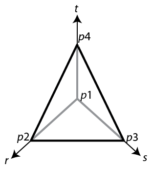
In local coordinates, the point p1 is at (0,0,0), p2 is at (1,0,0), p3 is at (0,1,0), and p4 is at (0,0,1).
For a linear tetrahedron, the basis functions are
For a quadratic tetrahedron, there are additional nodes at the edge midpoints.

The corresponding basis functions are
As in the 2-D case, a 3-D basis function ϕi takes the value 0 at all nodes j, except for node i, where it takes the value 1.
Partial Differential Equation Toolbox software can also handle systems of N partial differential equations over the domain Ω. We have the elliptic system
the parabolic system
the hyperbolic system
and the eigenvalue system
where c is an N-by-N-by-D-by-D tensor, and D is the geometry dimensions, 2 or 3.
For 2-D systems, the notation represents an N-by-1 matrix with an (i,1)-component
For 3-D systems, the notation represents an N-by-1 matrix with an (i,1)-component
The symbols a and d denote N-by-N matrices, and f denotes a column vector of length N.
The elements cijkl,
aij,
dij, and
fi of c,
a, d, and f are stored row-wise in the MATLAB® matrices c, a, d, and
f. The case of identity, diagonal, and symmetric matrices are handled
as special cases. For the tensor cijkl this
applies both to the indices i and j, and to the
indices k and l.
Partial Differential Equation Toolbox software does not check the ellipticity of the problem, and it is quite possible to define a system that is not elliptic in the mathematical sense. The preceding procedure that describes the scalar case is applied to each component of the system, yielding a symmetric positive definite system of equations whenever the differential system possesses these characteristics.
The boundary conditions now in general are mixed, i.e., for each point on the boundary a combination of Dirichlet and generalized Neumann conditions,
For 2-D systems, the notation represents an N-by-1 matrix with (i,1)-component
where the outward normal vector of the boundary is .
For 3-D systems, the notation represents an N-by-1 matrix with (i,1)-component
where the outward normal to the boundary is
There are M Dirichlet conditions and the h-matrix is M-by-N, M ≥ 0. The generalized Neumann condition contains a source , where the Lagrange multipliers μ are computed such that the Dirichlet conditions become satisfied. In a structural mechanics problem, this term is exactly the reaction force necessary to satisfy the kinematic constraints described by the Dirichlet conditions.
The rest of this section details the treatment of the Dirichlet conditions and may be skipped on a first reading.
Partial Differential Equation Toolbox software supports two implementations of Dirichlet conditions. The simplest is the “Stiff Spring” model, so named for its interpretation in solid mechanics. See Elliptic Equations for the scalar case, which is equivalent to a diagonal h-matrix. For the general case, Dirichlet conditions
hu = r
are approximated by adding a term
to the equations KU = F, where L is a large number such as 104 times a representative size of the elements of K.
When this number is increased, hu = r will be more accurately satisfied, but the potential ill-conditioning of the modified equations will become more serious.
The second method is also applicable to general mixed conditions with nondiagonal h, and is free of the ill-conditioning, but is more involved computationally. Assume that there are Np nodes in the mesh. Then the number of unknowns is NpN = Nu. When Dirichlet boundary conditions fix some of the unknowns, the linear system can be correspondingly reduced. This is easily done by removing rows and columns when u values are given, but here we must treat the case when some linear combinations of the components of u are given, hu = r. These are collected into HU = R where H is an M-by-Nu matrix and R is an M-vector.
With the reaction force term the system becomes
KU +H´ µ = F
HU = R.
The constraints can be solved for M of the U-variables, the remaining called V, an Nu – M vector. The null space of H is spanned by the columns of B, and U = BV + ud makes U satisfy the Dirichlet conditions. A permutation to block-diagonal form exploits the sparsity of H to speed up the following computation to find B in a numerically stable way. µ can be eliminated by pre-multiplying by B´ since, by the construction, HB = 0 or B´H´ = 0. The reduced system becomes
B´ KBV = B´ F – B´Kud
which is symmetric and positive definite if K is.
Version History
Introduced before R2006ahyperbolic is not recommended. Use solvepde instead. There are no plans to remove
hyperbolic.
You can now solve hyperbolic equations whose coefficients depend on the solution u or on the gradient of u.
See Also
MATLAB Command
You clicked a link that corresponds to this MATLAB command:
Run the command by entering it in the MATLAB Command Window. Web browsers do not support MATLAB commands.
Website auswählen
Wählen Sie eine Website aus, um übersetzte Inhalte (sofern verfügbar) sowie lokale Veranstaltungen und Angebote anzuzeigen. Auf der Grundlage Ihres Standorts empfehlen wir Ihnen die folgende Auswahl: .
Sie können auch eine Website aus der folgenden Liste auswählen:
So erhalten Sie die bestmögliche Leistung auf der Website
Wählen Sie für die bestmögliche Website-Leistung die Website für China (auf Chinesisch oder Englisch). Andere landesspezifische Websites von MathWorks sind für Besuche von Ihrem Standort aus nicht optimiert.
Amerika
- América Latina (Español)
- Canada (English)
- United States (English)
Europa
- Belgium (English)
- Denmark (English)
- Deutschland (Deutsch)
- España (Español)
- Finland (English)
- France (Français)
- Ireland (English)
- Italia (Italiano)
- Luxembourg (English)
- Netherlands (English)
- Norway (English)
- Österreich (Deutsch)
- Portugal (English)
- Sweden (English)
- Switzerland
- United Kingdom (English)