Simulieren Sie Trägheitssensorwerte aus einem Fahrszenario
Generieren Sie synthetische Sensordaten aus IMU, GPS und Radgebern mithilfe der Tools zur Fahrszenariogenerierung von Automated Driving Toolbox ™. Das drivingScenario-Objekt simuliert das Fahrszenario und aus den imuSensor-, gpsSensor- und wheelEncoderAckermann-Objekten werden Sensordaten generiert.
Szenario definieren
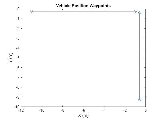
Erstellen Sie ein Fahrszenario mit einem Fahrzeug. Definieren Sie Wegpunkte, um das Fahrzeug vorwärtsfahren und abbiegen zu lassen. Um GPS-Messwerte zu simulieren, geben Sie den Referenzstandort in geodätischen Koordinaten an. Generieren Sie die Fahrzeugtrajektorie mit der Objektfunktion smoothTrajectory. Zeichnen Sie die Wegpunkte auf.
lla0 = [42 -71 50];
s = drivingScenario('GeoReference',lla0);
v = vehicle(s);

waypoints = [-11 -0.25 0;
    -1 -0.25 0;
    -0.6 -0.4 0;
    -0.6 -9.3 0];
speed = [1.5;0;0.5;1.5];
smoothTrajectory(v,waypoints,speed);

figure
plot(waypoints(:,1),waypoints(:,2),'-o')
xlabel('X (m)')
ylabel('Y (m)')
title('Vehicle Position Waypoints')
Sensoren erstellen
Erstellen Sie die IMU-, GPS- und Radgebersensoren. Geben Sie den Offset-Standort und die Winkel der IMU und des GPS an. Diese können bearbeitet werden, um die Montageposition und Ausrichtung der Sensoren am Fahrzeug zu ändern.
mountingLocationIMU = [1 2 3];
mountingAnglesIMU = [0 0 0];
% Convert orientation offset from Euler angles to quaternion.
orientVeh2IMU = quaternion(mountingAnglesIMU,'eulerd','ZYX','frame');
% ReferenceFrame must be specified as ENU.
imu = imuSensor('SampleRate',1/s.SampleTime,'ReferenceFrame','ENU');

mountingLocationGPS = [1 2 3];
mountingAnglesGPS = [50 40 30];
% Convert orientation offset from Euler angles to quaternion.
orientVeh2GPS = quaternion(mountingAnglesGPS,'eulerd','ZYX','frame');
% The GeoReference property in drivingScenario is equivalent to
% the ReferenceLocation property in gpsSensor.
% ReferenceFrame must be specified as ENU.
gps = gpsSensor('ReferenceLocation',lla0,'ReferenceFrame','ENU');

encoder = wheelEncoderAckermann('TrackWidth',v.Width,...
    'WheelBase',v.Wheelbase,'SampleRate',1/s.SampleTime);
Simulation ausführen
Führen Sie die Simulation aus und protokollieren Sie die generierten Sensorwerte.
% IMU readings.
accel = [];
gyro = [];
% Wheel encoder readings.
ticks = [];
% GPS readings.
lla = [];
gpsVel = [];
% Define the rate of the GPS compared to the simulation rate.
simSamplesPerGPS = (1/s.SampleTime)/gps.SampleRate;
idx = 0;
while advance(s)
    groundTruth = state(v);

    % Unpack the ground truth struct by converting the orientations from
    % Euler angles to quaternions and converting angular velocities form
    % degrees per second to radians per second.
    posVeh = groundTruth.Position;
    orientVeh = quaternion(fliplr(groundTruth.Orientation), 'eulerd', 'ZYX', 'frame');
    velVeh = groundTruth.Velocity;
    accVeh = groundTruth.Acceleration;
    angvelVeh = deg2rad(groundTruth.AngularVelocity);

    % Convert motion quantities from vehicle frame to IMU frame.
    [posIMU,orientIMU,velIMU,accIMU,angvelIMU] = transformMotion( ...
        mountingLocationIMU,orientVeh2IMU, ...
        posVeh,orientVeh,velVeh,accVeh,angvelVeh);
    [accel(end+1,:), gyro(end+1,:)] = imu(accIMU,angvelIMU,orientIMU);

    ticks(end+1,:) = encoder(velVeh, angvelVeh, orientVeh);

    % Only generate a new GPS sample when the simulation has advanced
    % enough.
    if (mod(idx, simSamplesPerGPS) == 0)
        % Convert motion quantities from vehicle frame to GPS frame.
        [posGPS,orientGPS,velGPS,accGPS,angvelGPS] = transformMotion(...
            mountingLocationGPS, orientVeh2GPS,...
            posVeh,orientVeh,velVeh,accVeh,angvelVeh);
        [lla(end+1,:), gpsVel(end+1,:)] = gps(posGPS,velGPS);
    end
    idx = idx + 1;
end
Ergebnisse visualisieren
Zeichnen Sie die generierten Sensorwerte auf.
figure
plot(ticks)
ylabel('Wheel Ticks')
title('Wheel Encoder')
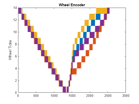
figure
plot(accel)
ylabel('m/s^2')
title('Accelerometer')

figure
plot(gyro)
ylabel('rad/s')
title('Gyroscope')

figure
geoplot(lla(:,1),lla(:,2))
title('GPS Position')
figure
plot(gpsVel)
ylabel('m/s')
title('GPS Velocity')
