Main Content

Baseband PLL

Phase-domain model of PLL

Since R2025a

  • Baseband PLL block

Libraries:
Mixed-Signal Blockset / PLL / Architectures

Description

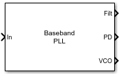
The Baseband PLL block models PLLs in the phase domain. The block accepts a real-valued phase offset vector and produces the outputs for a loop filter, phase detector, and VCO. The block acts as feedback control system that automatically adjusts the phase of a locally generated signal to match the phase of an input signal.

Examples

expand all

Open the model basebandPLLTB attached with this example.

model = 'basebandPLLTB';
open_system(model)

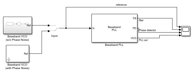
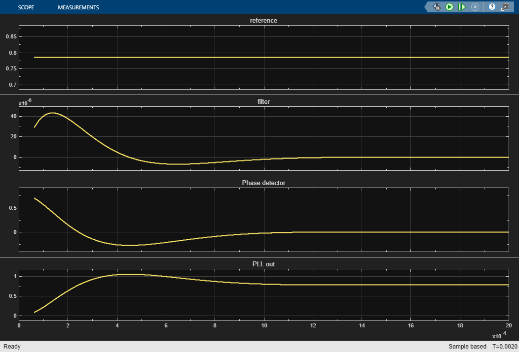
Connect the switch to the VCO without any phase noise. Run simulation.

set_param([model '/Input'],'sw','1');
sim(model);

To observe the effect of phase noise, change the switch position to connect the VCO with phase noise. Run simulation.

set_param([model '/Input'],'sw','0');
sim(model);

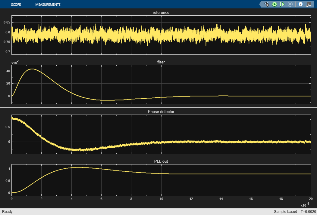
As you can see, even if you have a VCO signal with phase noise, the loop filter inside the Baseband PLL model is cleaning the effect of the phase noise to provide a clean PLL output.

Open the model basebandPLLLoopFilter attached with this example.

model = 'basebandPLLLoopFilter';
open_system(model)

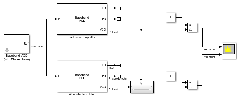
The model uses contains two loop filters, a 2nd-order passive loop filter and a 4th-order passive loop filter. All other parameters such as the loop bandwidth and phase margin are the same for both filters.

Run simulation to see the PLL outputs of both the filters.

sim(model);

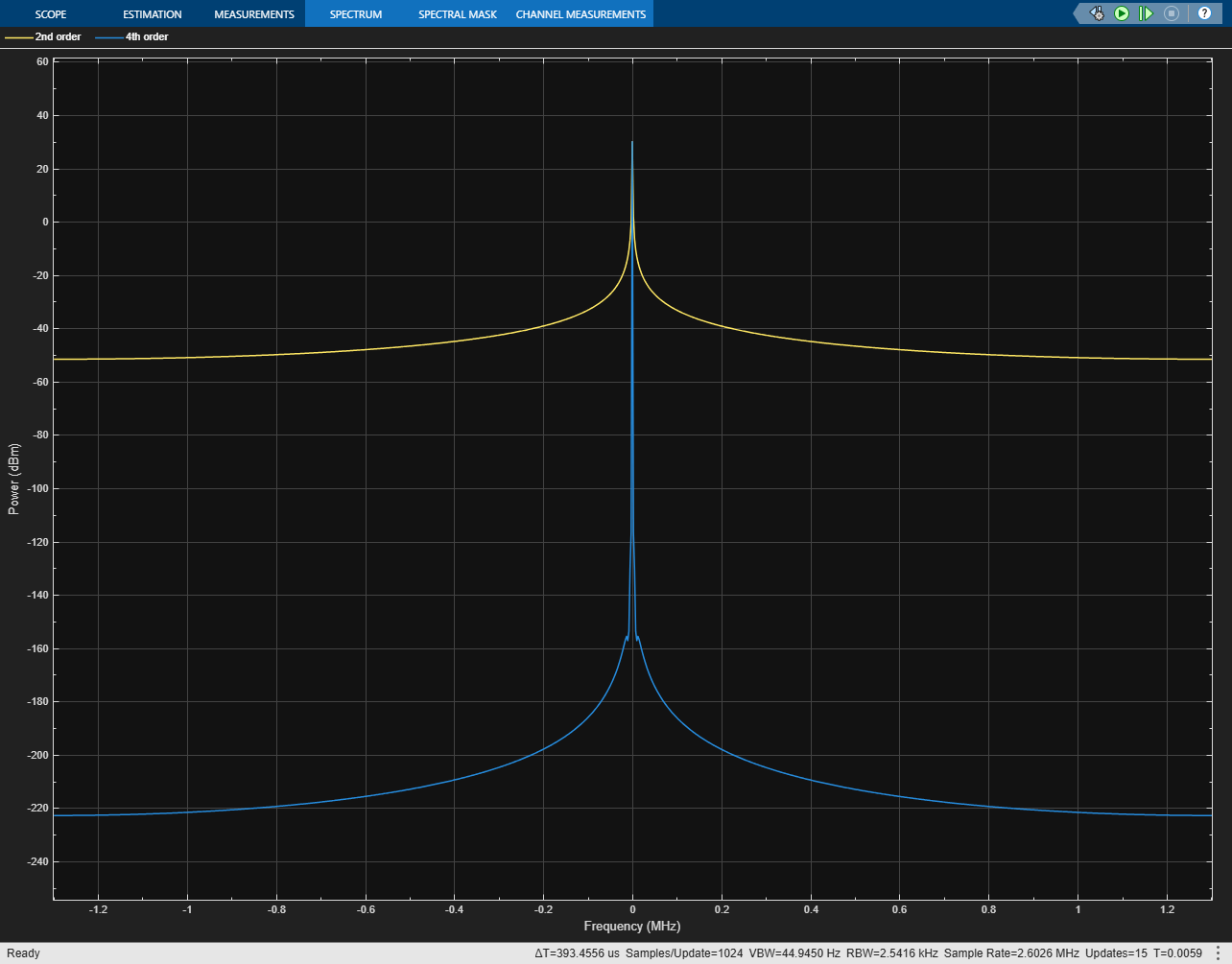
As you can see, the 4th-order loop filter better attenuates the noises at higher frequencies.

Ports

Input

expand all

Input signal, specified as a scalar. The input signal is the output of a baseband VCO in the phase domain.

Data Types: double

Output

expand all

Output of the loop filter in the phase domain, returned as a scalar.

Data Types: double

Output of the phase detector in the phase domain, returned as a scalar.

Data Types: double

Output of the VCO in the phase domain, returned as a scalar.

Data Types: double

Parameters

expand all

To edit block parameters interactively, use the Property Inspector. From the Simulink® Toolstrip, on the Simulation tab, in the Prepare gallery, select Property Inspector.

Determine how to define the loop filter. You can define a passive loop filter between the orders two to four, or you can represent a loop filter using transfer function.

If you are defining a passive loop filter, you have to define the Charge pump current (A), Min clock divider value. Loop bandwidth (Hz), and Phase margin (degrees) of the PLL system.

Programmatic Use

Block parameter: Ftype
Type: double
Values: Transfer function | 2nd order passive | 3rd order passive | 4th order passive
Default: Transfer function

Measure of change in output frequency for input voltage change, specified as a positive real scalar in Hz/V.

Programmatic Use

Block parameter: Kvco
Type: double
Values: positive real scalar
Default: 100e6

Full scale magnitude of the charge pump output current, specified as a positive real scalar in amperes.

Dependencies

To enable this parameter, set Loop filter type to 2nd order passive, 3rd order passive, or 4th order passive.

Programmatic Use

Block parameter: Icp
Type: double
Values: positive real scalar
Default: 5e3

Minimum value by which the clock divider can divide the input frequency, specified as a positive real scalar.

Dependencies

To enable this parameter, set Loop filter type to 2nd order passive, 3rd order passive, or 4th order passive.

Programmatic Use

Block parameter: Nmin
Type: double
Values: positive real scalar
Default: 100

Frequency at which the magnitude of the open loop transfer function becomes 1, specified as a positive real scalar in Hz. Lower values of Loop bandwidth (Hz) result in reduced phase noise and reference spurs at the expense of longer lock time and less phase margin.

Dependencies

To enable this parameter, set Loop filter type to 2nd order passive, 3rd order passive, or 4th order passive.

Programmatic Use

Block parameter: Fc
Type: double
Values: positive real scalar
Default: 50e3

Phase of the open loop transfer function at the loop bandwidth subtracted from 180°, specified as a positive real scalar in degrees. For optimum lock time, select a phase margin between 40° and 55°.

Dependencies

To enable this parameter, set Loop filter type to 2nd order passive, 3rd order passive, or 4th order passive.

Programmatic Use

Block parameter: phi
Type: double
Values: positive real scalar
Default: 45

Numerator of the loop filter transfer function. If you are defining a passive loop filter, this is automatically calculated for you. You can also manually change it if you are representing the loop filter using the transfer function.

Dependencies

To edit this parameter, set Loop filter type to Transfer function.

Programmatic Use

Block parameter: Fn
Type: double
Values: real scalar | real valued scalar
Default: [1.9212e-10, 5e-05]

Denominator of the loop filter transfer function. If you are defining a passive loop filter, this is automatically calculated for you. You can also manually change it if you are representing the loop filter using the transfer function.

Dependencies

To edit this parameter, set Loop filter type to Transfer function.

Programmatic Use

Block parameter: Fd
Type: double
Values: real valued vector
Default: [2.0157e-15, 3.0576e-09, 0]

Select to plot the gain margin and phase margin of the PLL system before simulation. By default, this option is selected.

Select to plot the pole-zero map, loop bandwidth, step response, and impulse response of the PLL system before simulation. You must have a license to Control System Toolbox™ to plot the step response and impulse response of the PLL system. By default, this option is selected.

Click to plot the presimulation loop dynamics of the PLL system.

Version History

Introduced in R2025a