Multiple Explicit MPC Controllers
Multiple explicit MPC controllers

Libraries:
Model Predictive Control Toolbox
Description
The Multiple Explicit MPC Controllers block uses the following input signals:
Measured plant outputs (
mo)Reference or setpoint (
ref)Measured plant disturbance (
md), if anySwitching signal (
switch)
The Multiple Explicit MPC Controllers block enables you to transition
between multiple explicit MPC controllers in real time based on the current operating
conditions. Typically, you design each controller for a particular region of the operating
space. Using available measurements, you detect the current operating region and select the
appropriate active controller using the switch inport.
The switching signal selects the active controller among a list of two or more candidate explicit MPC controllers. These controllers reduce online computational effort by using a table-lookup control law during each control interval instead of solving a quadratic programming problem. For more information, see Explicit MPC Controller.
To improve efficiency, inactive controllers do not evaluate their control law. However, to provide bumpless transfer between controllers, the inactive controllers continue to perform state estimation.
Like for the Multiple MPC Controllers block, you cannot disable evaluation for the Multiple Explicit MPC Controllers block. One controller must always be active.
Like the Explicit MPC Controller block, the Multiple Explicit MPC Controllers block supports only a subset of optional MPC features, as outlined in the following table.
| Supported Features | Unsupported Features |
|---|---|
|
|
Examples
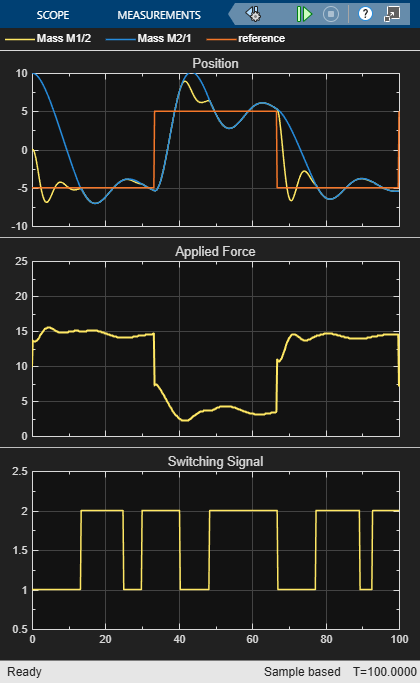
Gain-Scheduled Implicit and Explicit MPC Control of Mass-Spring System
Implement gain-scheduled MPC control of a nonlinear plant using the Multiple MPC Controllers block and Multiple Explicit MPC Controllers block.
Ports
Input
Output
Parameters
Extended Capabilities
Version History
Introduced in R2016b