How to Use Hall Validity and Hall Speed and Position Blocks
This example shows how to use Hall position sensors to obtain position feedback. The models in this example integrate the field-oriented control (FOC) algorithm with the Hall sensors and decode the rotor position and speed values.
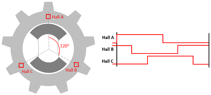
To determine the rotor position, direction of rotation, and an accurate rotor speed, you need at least three Hall sensors inside the motor. This assumes a hardware setup that uses a permanent magnet synchronous motor (PMSM) with three Hall sensors that are placed 120 degrees apart. As the rotor passes by the three sensors, the combination of measured binary values determines the six possible Hall states.
There are three methods to integrate the Hall Validity and Hall Speed and Position blocks into hardware, based on the number of interrupts available for Hall status changes and the number of timers (based on the hardware timer) attached to these interrupts. The following sections demonstrate these methods. Each example model contains a Hall Speed and Position block inside the Application Abstraction subsystem. The ADC End of Conversion interrupt, which triggers this subsystem, integrates into the rest of field-oriented control (FOC).
Single Hall Interrupt
You can integrate Hall decoder blocks into processors for which there is a common interrupt for status changes on any of the three Hall sensors, and one interrupt service routine (ISR) to service the interrupt.
Open the example model FOCUsingSingleHallInterrupt.
open_system('FOCUsingSingleHallInterrupt.slx');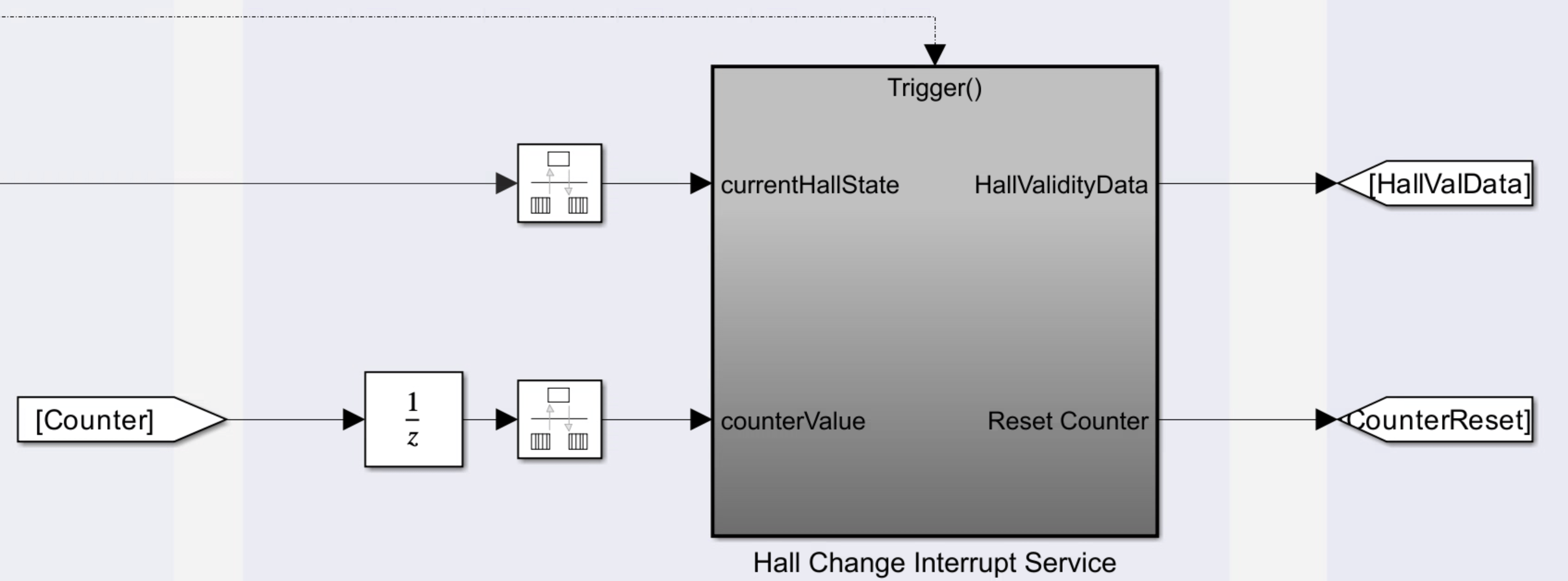
Expand the Microcontroller subsystem.
The Hall Change Interrupt Service subsystem contains a Hall Validity block inside the model reference HallValidityCodegen, and integrates into the ISR.
The Application Abstraction subsystem contains a Hall Speed and Position block inside the model reference HallDecoder60DegCodegen. The Speed measurement interval parameter for the Hall Speed and Position block is preconfigured to Every 60 Degrees as needed. Consider automatically capturing the timer value when the interrupt is triggered, if your processor provides this option. Otherwise, capture the timer value when the interrupt is triggered, then immediately reset the timer before servicing the rest of the ISR.
For an example where a single Hall interrupt and single timer is implemented on ST hardware, see Field-Oriented Control of PMSM with Hall Sensor Using STM32G4xx Based Processors (STM32 Microcontroller Blockset).
Three Hall Interrupts with Three Capture Timers
You can integrate Hall decoder blocks into processors for which there are three separate interrupts for status changes on each Hall sensor, and three ISRs to service each interrupt.
Open the example model FOCUsingThreeHallInterruptThreeTimers.
open_system('FOCUsingThreeHallInterruptThreeTimers.slx');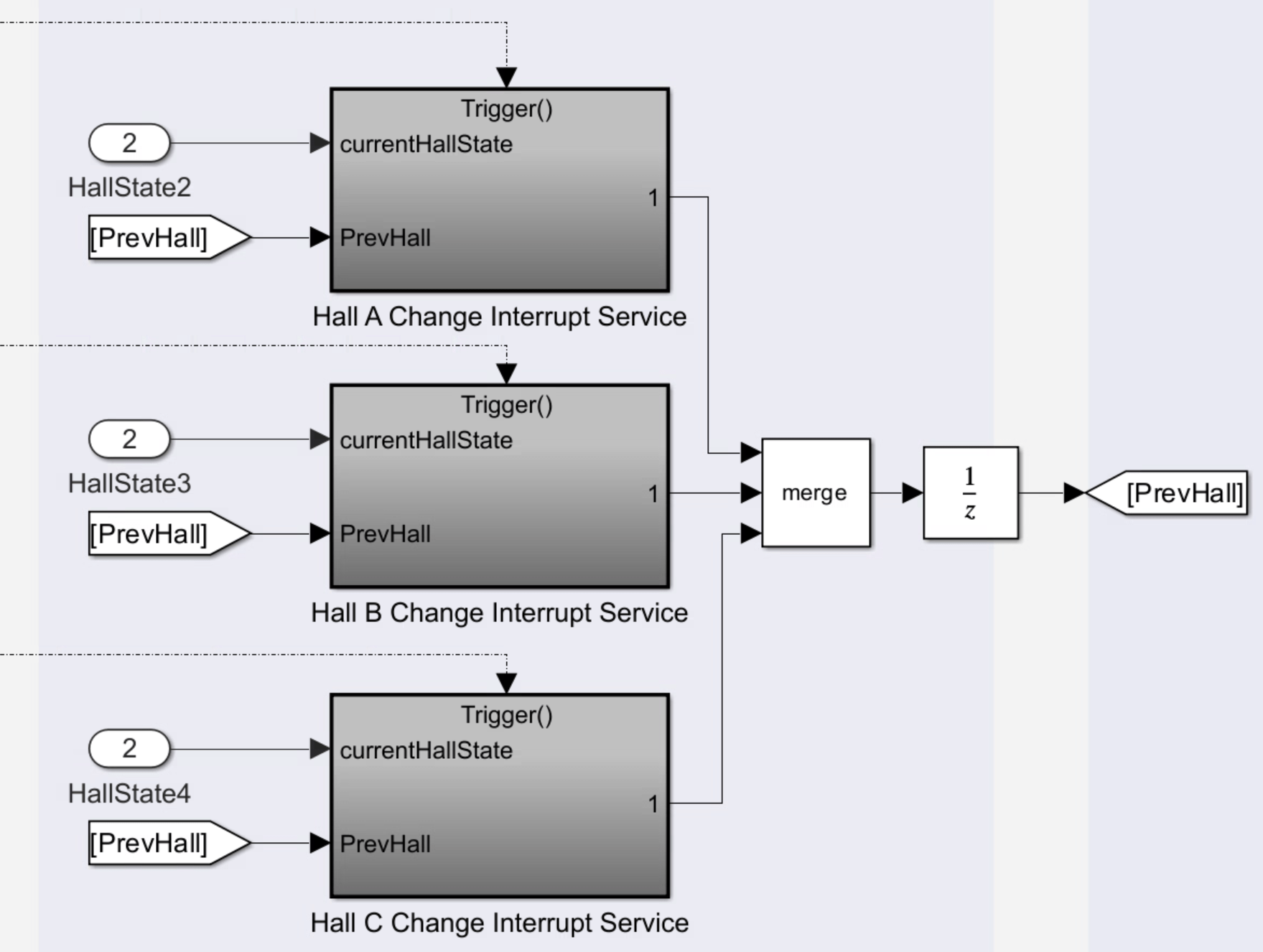
Expand the Microcontroller subsystem.
Each of the three Hall Change Interrupt Service subsystems contains a Hall Validity block inside the model reference HallValidityCodegen, and integrates into its own ISR.
The Application Abstraction subsystem contains a Hall Speed and Position block inside the model reference HallDecoder180DegCodegen. The Speed measurement interval parameter for the Hall Speed and Position block is preconfigured to Every 180 Degrees as needed (corresponding to the period of each timer). Consider automatically capturing the timer value when an interrupt is triggered, if your processor provides this option. Otherwise, capture the timer value when an interrupt is triggered, then immediately reset the timer before servicing the rest of the ISR.
For an example using a similar approach to implement FOC on C2 hardware, see Field-Oriented Control of PMSM Using Hall Sensor.
Three Hall Interrupts with Single Capture Timer
You can integrate Hall decoder blocks into processors for which there are three separate interrupts for status changes on each Hall sensor, and a single ISR to service all three interrupts.
Open the example model FOCUsingThreeHallInterruptSingleTimer (refer to the model diagram in the last section).
open_system('FOCUsingThreeHallInterruptSingleTimer.slx');Expand the Microcontroller subsystem.
Each of the three Hall Change interrupt Service subsystems contains a Hall Validity block inside the model reference HallValidityCodegen, and integrates into its own ISR.
The Application Abstraction subsystem contains a Hall Speed and Position block inside the model reference HallDecoder60DegCodegen. The Speed measurement interval parameter for the Hall Speed and Position block is preconfigured to Every 60 Degrees as needed. Consider automatically capturing the timer value when an interrupt is triggered, if your processor provides this option. Otherwise, capture the timer value when an interrupt is triggered, then immediately reset the timer before servicing the rest of the ISR.
Export Model Algorithm by Generating Code
To export the model algorithm, generate code from the model references HallValidityCodegen and HallDecoder60DegCodegen or HallDecoder180DegCodegen. This step requires that you have a Simulink Coder® license.
Refer to the example model to understand how to integrate the generated code with your custom code. For instance, the models with three ISRs employ data stores (implemented as global variables in the generated code) to interface among the Hall Speed and Position block and the three Hall Validity blocks. Since each Hall Change Interrupt Service subsystem contains an instance of HallValidityCodegen, you can call the same entry point functions for all three ISRs.