Main Content

Double-Acting Actuator (G)

Double-acting linear actuator in a gas network

Since R2023b

Libraries:
Simscape / Fluids / Gas / Actuators

Description

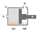
The Double-Acting Actuator (G) block models a linear actuator with a piston controlled by two opposing gas chambers. The actuator generates force in the extension and retraction strokes. The generated force depends on the pressure difference between the two chambers.

The figure shows the key components of the actuator. Ports A and B represent the gas chamber inlets. Port R represents the translating actuator piston and port C represents the actuator case. Ports HA and HB represent the thermal interfaces between each gas chamber and the environment. The moving piston is adiabatic.

Double-Acting Actuator Schematic

Displacement

The block measures the piston displacement as the position at port R relative to port C. The Mechanical orientation parameter identifies the direction of piston displacement. The piston displacement is neutral, or 0, when the chamber A volume is equal to the value of the Dead volume in chamber A parameter. When the Piston displacement from chamber A cap parameter is Provide input signal from Multibody joint, you input the piston displacement using port p. Ensure that the derivative of the position signal is equal to the piston velocity. You can ensure that the derivative of the position signal is equal to the piston velocity by using a Translational Multibody Interface block to provide the piston displacement.

The direction of the piston motion depends on the Mechanical orientation parameter. If the mechanical orientation is positive, then the piston translation is positive in relation to the actuator case when the gauge pressure at port A is positive. The direction of motion reverses when the mechanical orientation is negative.

Hard Stop

A set of hard stops limit the piston range of motion. The block uses an implementation of the Translational Hard Stop block, which treats hard stops like spring-damper systems. The spring stiffness coefficient controls the restorative component of the hard-stop contact force and the damping coefficient the dissipative component.

The hard stops are located at the distal ends of the piston stroke. If the mechanical orientation is positive, then the lower hard stop is at x = 0, and the upper hard stop is at x = +stroke. If the mechanical orientation is negative, then the lower hard stop is at x = -stroke, and the upper hard stop is at x = 0.

Block Composite

This block is a composite component based on these Simscape™ Foundation blocks:

Diagram of elements that make up the block.

Ports

Input

expand all

Physical signal input associated with the piston position, in m. Connect this port to a Simscape Multibody™ network using a Translational Multibody Interface block.

Dependencies

To enable this port, set Piston displacement from chamber A cap to Provide input signal from Multibody joint.

Output

expand all

Physical signal port associated with the piston position.

Dependencies

To enable this port, set Piston displacement from chamber A cap to Calculate from velocity of port R relative to port C.

Conserving

expand all

Gas conserving port associated with the inlet to chamber A.

Gas conserving port associated with the inlet to chamber B.

Mechanical translational conserving port associated with the actuator piston.

Mechanical translational conserving port associated with the actuator casing.

Thermal conserving port associated with chamber A.

Thermal conserving port associated with chamber B.

Parameters

expand all

Actuator

Whether to model the same fluid in both actuator chambers. If you select this parameter, the actuator propagates fluid properties through both chambers. Clear this parameter to model each chamber as a different fluid, where each chamber is connected to an isolated fluid network.

Piston displacement direction. When you set this parameter to:

  • Pressure at A causes positive displacement of R relative to C, the piston displacement is positive when the volume of gas at port A is expanding. This motion corresponds to rod extension.

  • Pressure at A causes negative displacement of R relative to C, the piston displacement is negative when the volume of gas at port A is expanding. This motion corresponds to rod contraction.

Cross-sectional area of the piston rod on the chamber A side.

Cross-sectional area of the piston rod on the chamber B side.

Maximum piston travel distance.

Volume of gas when the piston displacement is 0 in chamber A. This parameter is the gas volume when the piston is against the actuator end cap.

Volume of gas when the piston displacement is 0 in chamber B. This parameter is the gas volume when the piston is against the actuator end cap.

Cross-sectional area of port A.

Cross-sectional area of port B.

Environment reference pressure. When you select Atmospheric pressure, the block assumes a pressure of 0.101325 MPa.

User-defined environmental pressure.

Dependencies

To enable this parameter, set Environment pressure specification to Specified pressure.

Hard Stop

Hard stop model to use when the piston is at full extension or full extraction. See the Translational Hard Stop block for more information.

Piston stiffness coefficient.

Dependencies

To enable this parameter, set Hard stop model to one of these settings:

  • Stiffness and damping applied smoothly through transition region, damped rebound

  • Full stiffness and damping applied at bounds, undamped rebound

  • Full stiffness and damping applied at bounds, damped rebound

Piston damping coefficient.

Dependencies

To enable this parameter, set Hard stop model to one of these settings:

  • Stiffness and damping applied smoothly through transition region, damped rebound

  • Full stiffness and damping applied at bounds, undamped rebound

  • Full stiffness and damping applied at bounds, damped rebound

Application range of the hard stop force model. The block does not apply the hard stop model when the maximum extension or retraction of the piston is outside of this range. In this situation, there is no additional force on the piston.

Dependencies

To enable this parameter, set Hard stop model to Stiffness and damping applied smoothly through transition region, damped rebound.

Ratio of the final to the initial relative speed between the slider and the stop after the slider bounces.

Dependencies

To enable this parameter, set Hard stop model to Based on coefficient of restitution.

Threshold relative speed between the slider and stop before collision. When the slider hits the case with a speed less than the value of the Static contact speed threshold parameter, they stay in contact. Otherwise, the slider bounces. To avoid modeling static contact between the slider and the case, set this parameter to 0.

Dependencies

To enable this parameter, set Hard stop model to Based on coefficient of restitution.

Minimum force needed to release the slider from a static contact mode.

Dependencies

To enable this parameter, set Hard stop model to Based on coefficient of restitution.

Initial Conditions

Method for determining the piston position. The block can receive the position from a Multibody block when set to Provide input signal from Multibody joint, or can calculate the position internally and report the position at port p. The position is between 0 and the value of the Piston stroke parameter when the mechanical orientation is positive and between 0 and the negative value of the Piston stroke parameter when the mechanical orientation is negative.

Piston position at the start of the simulation with respect to the chamber A cap.

Dependencies

To enable this parameter, set Piston displacement to Calculate from velocity of port R relative to port C.

Starting gas pressure in chamber A.

Starting gas pressure in chamber B.

Initial temperature of the gas volume in the actuator.

Initial temperature of the gas volume in the actuator.

Extended Capabilities

C/C++ Code Generation
Generate C and C++ code using Simulink® Coder™.

Version History

Introduced in R2023b

expand all