Generate Cosimulation Model
Requirements
To use this feature, your installation must include an HDL Verifier™ license.
Make sure the DUT subsystem has no unconnected output ports. See Terminate Unconnected Block Outputs and Usage of Commenting Blocks.
What Is Cosimulation Model?
A cosimulation model is an automatically generated Simulink® model configured for both Simulink simulation and cosimulation of your design with an HDL simulator. HDL Coder™ supports automatic generation of a cosimulation model as a part of the test bench generation process.
The cosimulation model includes:
A behavioral model of your design, realized in a Simulink subsystem.
A corresponding HDL Cosimulation block, configured to cosimulate the design using HDL Verifier. HDL Coder configures the HDL Cosimulation block for use with either Siemens® ModelSim™, Cadence Incisive®, Synopsys® VCS®, or Xilinx® Vivado® simulator.
Test input data, calculated from the test bench stimulus that you specify.
Scope blocks, which let you observe and compare the DUT and HDL cosimulation outputs, and any error between these signals.
Goto and From blocks that capture the stimulus and response signals from the DUT and use these signals to drive the cosimulation.
A comparison/assertion mechanism that reports discrepancies between the original DUT output and the cosimulation output.
In addition to the generated model, HDL Coder generates a TCL script that launches and configures your cosimulation tool. Comments in the script file document clock, reset, and other timing signal information defined by the code generator for the cosimulation tool.
Generating Cosimulation Model Using Model Configuration Parameters
This example demonstrates the process for generating a cosimulation model. The example
model, hdl_cosim_demo1, implements a simple multiply and accumulate (MAC)
algorithm. Open the model by entering the name at the MATLAB® command line:
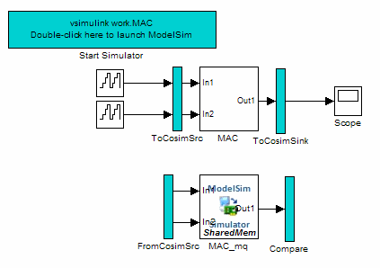
openExample('hdl_cosim_demo1');This figure shows the top-level model.

The DUT is the MAC subsystem.

Cosimulation model generation takes place during generation of the test bench. As a best practice, generate HDL code before generating a test bench, as follows:
Open the Configuration Parameters dialog box. Right-click on the white space of the Simulink model and select Model Configuration Parameters.
In the HDL Code Generation pane of the Configuration Parameters dialog box, set Generate HDL for to
hdl_cosim_demo1/MAC.Click Apply.
Click Generate. HDL Coder displays progress messages, as shown in this listing:
### Applying HDL Code Generation Control Statements
### Starting HDL Check.
### HDL Check Complete with 0 error, 0 warning and 0 message.

### Begin VHDL Code Generation
### Working on hdl_cosim_demo1/MAC as hdlsrc\MAC.vhd
### HDL Code Generation Complete.
Next, configure the test bench options to include generation of a cosimulation model:
Select the HDL Code Generation > Test Bench pane of the Configuration Parameters dialog box.
Select your Simulation tool in the drop-down menu. Then select the Cosimulation model check box.
Configure required test bench options. HDL Coder records option settings in a generated script file (see The Cosimulation Script File).
Click Apply.
Next, generate test bench code and the cosimulation model:
At the bottom of the Test Bench pane, click Generate Test Bench. HDL Coder displays progress messages as shown in this listing:
### Begin TestBench Generation
### Generating new cosimulation model: gm_hdl_cosim_demo1_mq0.mdl
### Generating new cosimulation tcl script: hdlsrc/gm_hdl_cosim_demo1_mq0_tcl.m
### Cosimulation Model Generation Complete.

### Generating Test bench: hdlsrc\MAC_tb.vhd
### Please wait ...
### HDL TestBench Generation Complete.
When test bench generation completes, HDL Coder opens the generated cosimulated model. This figure shows the generated model.
Save the generated model. The generated model exists only in memory unless you save it.
As indicated by the code generation messages, HDL Coder generates these files in addition to the usual HDL test bench file:
A cosimulation model (
gm_hdl_cosim_demo1_mq)A file that contains a TCL cosimulation script and information about settings of the cosimulation model (
gm_hdl_cosim_demo1_mq_tcl.m)
Generated file names derive from the model name, as described in Naming Conventions for Generated Cosimulation Models and Scripts.
The next section, Structure of Generated Model, describes the features of the model. Before running a cosimulation, become familiar with these features.
Structure of Generated Model
You can set up and launch a cosimulation using controls located in the generated model. This section examines the model generated from the example MAC subsystem.
Simulation Path
The model comprises two parallel signal paths. The simulation path, located in the upper half of the model window, is nearly identical to the original DUT. The purpose of the simulation path is to execute a normal Simulink simulation and provide a reference signal for comparison to the cosimulation results. This figure shows the simulation path.

The two subsystems labeled ToCosimSrc and
ToCosimSink do not change the
performance of the simulation path. Their purpose is to
capture stimulus and response signals of the DUT and route them to and from the HDL
cosimulation block (see Signal Routing Between Simulation and Cosimulation Paths).
Cosimulation Path
The cosimulation path, located in the lower half of the model window, contains the generated HDL Cosimulation block. This figure shows the cosimulation path.

The FromCosimSrc subsystem receives the same input signals that
drive the DUT. In the gm_hdl_cosim_demo1_mq0 model, the subsystem
simply passes the inputs on to the HDL Cosimulation block. Signals of some
other data types require further processing at this stage (see Signal Routing Between Simulation and Cosimulation Paths).
The Compare subsystem at the end of the cosimulation path compares
the cosimulation output to the reference output produced by the simulation path. If the
comparison detects a discrepancy, an Assertion block in the Compare
subsystem displays a warning message. If desired, you can disable assertions and control
other operations of the Compare subsystem. See Controlling Assertions and Scope Displays for details.
HDL Coder populates the HDL Cosimulation block with the compiled I/O
interface of the DUT. This figure shows the Ports pane of the
Mac_mq
HDL Cosimulation block.
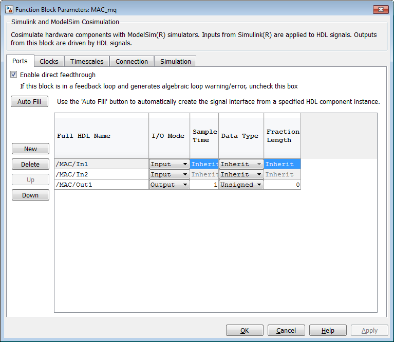
HDL Coder sets the Full HDL Name, Sample Time, Data Type, and other fields as required by the model. HDL Coder also configures other HDL Cosimulation block parameters under the Timescales and Tcl panes.
Tip
HDL Coder configures the generated HDL Cosimulation block for the
Shared Memory connection method.
Start Simulator Control
ModelSim or Incisive® users — When you double-click the Start Simulator control, it launches the selected cosimulation tool and passes in a startup command to the tool. The Start Simulator icon displays the startup command, as shown in this figure.

The commands executed when you double-click the Start Simulator icon launch and set up the cosimulation tool, but they do not start the actual cosimulation. Launching Cosimulation describes how to run a cosimulation with the generated model.
Synopsys VCS users — When you double-click the Start Simulator control, it launches the selected cosimulation tool and passes in a startup command to the tool. This figure displays the Start Simulator icon for the Synopsys VCS simulator.

The commands executed when you double-click the Start Simulator icon launch and set up the cosimulation tool, but they do not start the actual cosimulation. Launching Cosimulation for Synopsys VCS describes how to run a cosimulation with the generated model.
Vivado simulator users — When you double-click the Start Simulator control, it regenerates a shared library (DLL file). The Start Simulator icon displays that information, as shown in this figure.

Signal Routing Between Simulation and Cosimulation Paths
The generated model routes signals between the simulation and cosimulation paths using
Goto and From blocks. For example, the Goto blocks in the ToCosimSrc
subsystem route each DUT input signal to a corresponding From block in the
FromCosimSrc subsystem. These figures show the Goto and From blocks
in each subsystem.


The preceding figures show simple scalar inputs. Signals of complex and vector data types require further processing. See Complex and Vector Signals in Generated Cosimulation Model for further information.
Controlling Assertions and Scope Displays
The Compare subsystem lets you control the display of signals on
scopes, and warning messages from assertions. This figure shows the
Compare subsystem for the gm_hdl_cosim_demo1_mq0
model.
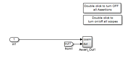
For each output of the DUT, HDL Coder generates an assertion checking subsystem (Assert_OutN
). The subsystem computes the difference (err)
between the original DUT output (dut ref) and the corresponding
cosimulation output (cosim). The subsystem routes the comparison result
to an Assertion block. If the comparison result is not zero, the Assertion block reports
the discrepancy.
This figure shows the Assert_Out1 subsystem for the
gm_hdl_cosim_demo1_mq0 model.

This subsystem also routes the dut ref, cosim,
and err signals to a Scope for display at the top level of the
model.
By default, the generated cosimulation model enables all
assertions and displays all Scopes. Use the buttons on the
Compare subsystem to disable assertions or hide Scopes.
Tip
Assertion messages are warnings and do not stop simulation.
Launching Cosimulation
To run a cosimulation with the generated model:
Double-click the
Comparesubsystem to configure Scopes and assertion settings.If you want to disable Scope displays or assertion warnings before starting your cosimulation, use the buttons on the
Comparesubsystem (shown in this figure).Double-click the Start Simulator control.
The Start Simulator control launches your HDL simulator (in this case, HDL Verifier for use with Siemens ModelSim).
The HDL simulator, in turn, executes a startup script. In this case, the startup script consists of the TCL commands located in
gm_hdl_cosim_demo1_mq0_tcl.m. When the HDL simulator finishes executing the startup script, it displays a message like this:# Ready for cosimulation...
In the Simulink Editor for the generated model, start simulation.
As the cosimulation runs, the HDL simulator displays messages like these:
# Running Simulink Cosimulation block.
# Chip Name: --> hdl_cosim_demo1/MAC
# Target language: --> vhdl
# Target directory: --> hdlsrc
# Fri Jun 05 4:26:34 PM Eastern Daylight Time 2009
# Simulation halt requested by foreign interface.
# done
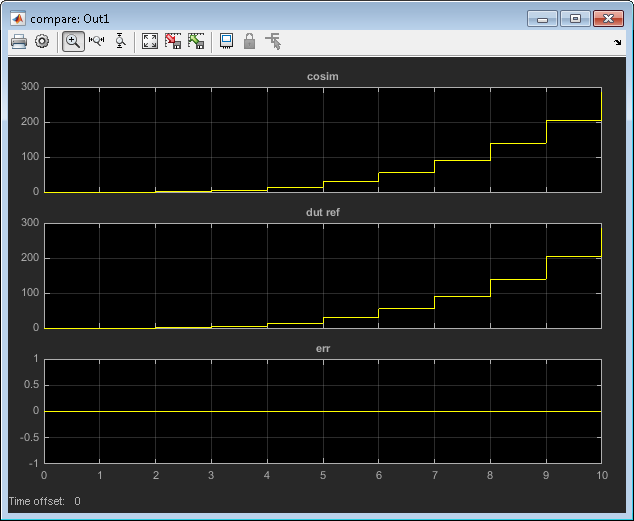
At the end of the cosimulation, if you have enabled Scope displays, the compare scope displays these signals:
cosim: The result signal output by the HDL Cosimulation block.dut ref: The reference output signal from the DUT.err: The difference (error) between these two outputs.
This figure shows these signals.
Launching Cosimulation for Synopsys VCS
To run a cosimulation with the generated model for the Synopsys VCS simulator:
Double-click the
Comparesubsystem to configure Scopes and assertion settings.If you want to disable Scope displays or assertion warnings before starting your cosimulation, use the buttons on the
Comparesubsystem (shown in this figure).Double-click the Start Simulator control.
The Start Simulator control starts your HDL simulator (in this case, HDL Verifier for use with Synopsys VCS).
The HDL simulator, in turn, executes a startup script. In this case, the startup script consists of the
launchVCS(HDL Verifier) function located ingm_hdl_cosim_demo1_vc_cosim.m. When the HDL simulator finishes executing the startup script, it starts the VCS simulator.Establish the connection between the VCS simulator and Simulink by executing this command at the VCS command prompt:
run
This command makes the HDL simulator ready for cosimulation.
In the Simulink Editor for the generated model, start simulation.
At the end of the cosimulation, if you have enabled Scope displays, the compare scope displays these signals:
cosim: The result signal output by the HDL Cosimulation block.dut ref: The reference output signal from the DUT.err: The difference (error) between these two outputs.
Generate the code coverage report for your generated test bench by executing this command at the VCS command prompt:
do cosimVCS.postsim.tcl
Note
You can generate the code coverage report only when you select HDL code coverage in the HDL Code Generation > Test Bench pane of the Configuration Parameters dialog box.
To restart cosimulation, execute these commands at the VCS command prompt:
restart
do cosimVCS.presim.tcl
run
The Cosimulation Script File
The generated script file has two sections:
A comment section that documents model settings that are relevant to cosimulation.
A function that stores several lines of TCL code into a variable,
tclCmds. The cosimulation tools execute these commands when you launch a cosimulation.
Header Comments Section
This listing shows the comment section of a script file generated for the
hdl_cosim_demo1 model:
%%%%%%%%%%%%%%%%%%%%%%%%%%%%%%%%%%%%%%%%%%%%%%%%%%%%%%%%%%%%%%%%%%%%%%%%%%%
% Auto generated cosimulation 'tclstart' script
%%%%%%%%%%%%%%%%%%%%%%%%%%%%%%%%%%%%%%%%%%%%%%%%%%%%%%%%%%%%%%%%%%%%%%%%%%%
%  Source Model         : hdl_cosim_demo1.mdl
%  Generated Model      : gm_hdl_cosim_demo1.mdl
%  Cosimulation Model   : gm_hdl_cosim_demo1_mq.mdl
%
%  Source DUT           : gm_hdl_cosim_demo1_mq/MAC
%  Cosimulation DUT     : gm_hdl_cosim_demo1_mq/MAC_mq
%
%  File Location        : hdlsrc/gm_hdl_cosim_demo1_mq_tcl.m
%  Created              : 2009-06-16 10:51:01
%
%  Generated by MATLAB 7.9 and HDL Coder 1.6
%%%%%%%%%%%%%%%%%%%%%%%%%%%%%%%%%%%%%%%%%%%%%%%%%%%%%%%%%%%%%%%%%%%%%%%%%%%

%%%%%%%%%%%%%%%%%%%%%%%%%%%%%%%%%%%%%%%%%%%%%%%%%%%%%%%%%%%%%%%%%%%%%%%%%%%
%  ClockName           : clk
%  ResetName           : reset
%  ClockEnableName     : clk_enable
%
%  ClockLowTime        : 5ns
%  ClockHighTime       : 5ns
%  ClockPeriod         : 10ns
%
%  ResetLength         : 20ns
%  ClockEnableDelay    : 10ns
%  HoldTime            : 2ns
%%%%%%%%%%%%%%%%%%%%%%%%%%%%%%%%%%%%%%%%%%%%%%%%%%%%%%%%%%%%%%%%%%%%%%%%%%%

%%%%%%%%%%%%%%%%%%%%%%%%%%%%%%%%%%%%%%%%%%%%%%%%%%%%%%%%%%%%%%%%%%%%%%%%%%%
%  ModelBaseSampleTime   : 1
%  OverClockFactor     : 1
%%%%%%%%%%%%%%%%%%%%%%%%%%%%%%%%%%%%%%%%%%%%%%%%%%%%%%%%%%%%%%%%%%%%%%%%%%%

%%%%%%%%%%%%%%%%%%%%%%%%%%%%%%%%%%%%%%%%%%%%%%%%%%%%%%%%%%%%%%%%%%%%%%%%%%%
%  Mapping of DutBaseSampleTime to ClockPeriod
%
%  N = (ClockPeriod / DutBaseSampleTime) * OverClockFactor
%  1 sec in Simulink corresponds to 10ns in the HDL
%  Simulator(N = 10)
%
%%%%%%%%%%%%%%%%%%%%%%%%%%%%%%%%%%%%%%%%%%%%%%%%%%%%%%%%%%%%%%%%%%%%%%%%%%%

%%%%%%%%%%%%%%%%%%%%%%%%%%%%%%%%%%%%%%%%%%%%%%%%%%%%%%%%%%%%%%%%%%%%%%%%%%%
%  ResetHighAt          : (ClockLowTime + ResetLength + HoldTime)
%  ResetRiseEdge        : 27ns
%  ResetType            : async
%  ResetAssertedLevel   : 1
%
%  ClockEnableHighAt    : (ClockLowTime + ResetLength + ClockEnableDelay + HoldTime)
%  ClockEnableRiseEdge  : 37ns
%%%%%%%%%%%%%%%%%%%%%%%%%%%%%%%%%%%%%%%%%%%%%%%%%%%%%%%%%%%%%%%%%%%%%%%%%%%
The comments section comprises these subsections:
Header comments: This section documents the files names for the source and generated models and the source and generated DUT.
Test bench settings: This section documents the
makehdltbproperty values that affect cosimulation model generation. The generated TCL script uses these values to initialize the cosimulation tool.Sample time information: The next two sections document the base sample time and oversampling factor of the model. HDL Coder uses
ModelBaseSampleTimeandOverClockFactorto map the clock period of the model to the HDL cosimulation clock period.Clock, clock enable, and reset waveforms: This section documents the computations of the duty cycle of the
clk,clk_enable, andresetsignals.
TCL Commands Section
This listing shows the TCL commands section of a script file generated for the
hdl_cosim_demo1 model:
function tclCmds = gm_hdl_cosim_demo1_mq_tcl
tclCmds = {
    'do MAC_compile.do',...% Compile the generated code
    'vsimulink work.MAC',...% Initiate cosimulation
    'add wave  /MAC/clk',...% Add wave commands for chip input signals
    'add wave  /MAC/reset',...
    'add wave  /MAC/clk_enable',...
    'add wave  /MAC/In1',...
    'add wave  /MAC/In2',...
    'add wave  /MAC/ce_out',...% Add wave commands for chip output signals
    'add wave  /MAC/Out1',...
    'set UserTimeUnit ns',...% Set simulation time unit
    'puts ""',...
    'puts "Ready for cosimulation..."',...
};
end
Complex and Vector Signals in Generated Cosimulation Model
Input signals of complex or vector data types require insertion of additional elements into the cosimulation path. this section describes these elements.
Complex Signals
The generated cosimulation model automatically breaks complex inputs into real and
imaginary parts. This figure shows a FromCosimSrc subsystem that
receives two complex input signals. The subsystem breaks the inputs into real and
imaginary parts before passing them to the subsystem outputs.

The model maintains the separation of real and imaginary components throughout the
cosimulation path. The Compare subsystem performs separate comparisons
and separate scope displays for the real and imaginary signal components.
Vector Signals
The generated cosimulation model flattens vector inputs. This figure shows a
FromCosimSrc subsystem that receives two vector input signals of
dimension 2. The subsystem flattens the inputs into scalars before passing them to the
subsystem outputs.

Generating Cosimulation Model from Command Line
To generate a cosimulation model from the command line, pass the
GenerateCosimModel property to the makehdltb
function. GenerateCosimModel takes one of these property values:
'ModelSim': Generate a cosimulation model configured for HDL Verifier for use with Siemens ModelSim.'Incisive': Generate a cosimulation model configured for HDL Verifier for use with Cadence Incisive.'VCS': Generate a cosimulation model configured for HDL Verifier for use with Synopsys VCS.'Vivado Simulator': Generate a cosimulation model configured for HDL Verifier for use with Xilinx Vivado.
In this command, makehdltb generates a cosimulation model
configured for HDL Verifier for use with Siemens
ModelSim.
makehdltb('hdl_cosim_demo1/MAC','GenerateCosimModel','ModelSim');
Naming Conventions for Generated Cosimulation Models and Scripts
The naming convention for generated cosimulation models is
prefix_modelname_toolid_suffix,
where:
prefixis the stringgm.modelnameis the name of the generating model.toolidis an identifier indicating the HDL simulator chosen by the Cosimulation model for use with: option. Validtoolidstrings are'mq','in','vc', or'vs'.suffix is an integer that provides each generated model with a unique name. The suffix increments with each successive test bench generation for a given model. For example, if the original model name is
test, then the sequence of generated cosimulation model names isgm_test_toolid_0,gm_test_toolid_1, and so on.
The naming convention for generated cosimulation scripts is the same as that for models,
except that the file name extension is .m.
Limitations for Cosimulation Model Generation
When you configure a model for cosimulation model generation, observe these limitations:
Explicitly specify the sample times of source blocks to the DUT in the simulation path. Use of the default sample time (
-1) in the source blocks may cause sample time propagation problems in the cosimulation path of the generated model.The HDL Coder software does not support continuous sample times for cosimulation model generation. Do not use sample times
0orInfin source blocks in the simulation path.If you set Clock Inputs to
Multiple, HDL Coder does not support generation of a cosimulation model.Combinatorial output paths (caused by absence of registers in the generated code) have a latency of one extra cycle in cosimulation. To avoid discrepancy in the comparison between the simulation and cosimulation outputs, the Allow direct feedthrough option on the Ports pane of the HDL Cosimulation block is automatically selected.
Alternatively, you can avoid the latency by specifying output pipelining (see OutputPipeline). This will fully register outputs during code generation.
Double data types are not supported for the HDL Cosimulation block. Avoid use of double data types in the simulation path when generating HDL code and a cosimulation model.