Generate Software Interface Model to Probe and Rapidly Prototype HDL IP Core
When you run the hardware-software co-design workflow for SoC platforms, you generate an HDL IP core for the DUT algorithm, and then integrate the IP core into the reference design. See Hardware-Software Co-Design Workflow for SoC Platforms.
To test the HDL IP core on the target hardware, generate a software interface model. The software interface model uses AXI driver blocks to test the HDL IP core functionality in external mode simulation.
Prerequisites
A target platform, such as ZedBoard, where you want to deploy your software interface model.
The latest version of the third-party synthesis tool, such as Xilinx® Vivado®. See HDL Language Support and Supported Third-Party Tools and Hardware. In your MATLAB® session, set the path to that installed synthesis tool by using the
hdlsetuptoolpathfunction.If you are generating the software interface model, install Embedded Coder® and Simulink® Coder™.
Install the HDL Coder™ and Embedded Coder support packages for the target platform. On the MATLAB Toolstrip, click Home > Add-Ons > Get Add-Ons button. See Get and Manage Add-Ons.
Generate Software Interface
When running the IP core generation workflow, you can generate a host interface script and software interface model from the HDL Workflow Advisor UI or at the command line.
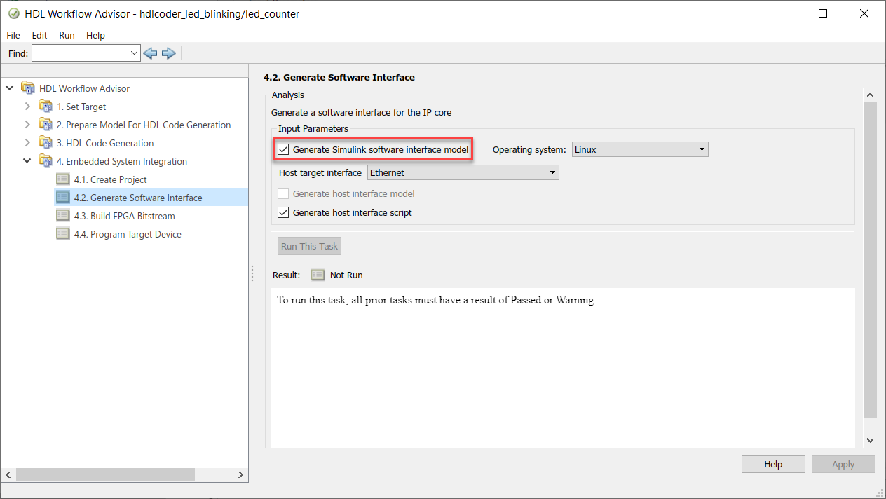
From the UI, in the Embedded System Integration > Generate Software Interface task, select the Generate Simulink software interface model check box.

If you are targeting standalone FPGA boards, you cannot generate a software interface model. Instead, you can generate a host interface script and test the IP core by using the AXI Manager driver.
In the Set Target Reference Design task, set Insert AXI Manager (HDL Verifier required) to
JTAGorEthernetbased on the interface that communicates between your host machine and the FPGA board. For Ethernet, specify the IP address of the FPGA board using the Board IP Address parameter.Note
By default, the
Ethernetoption is available for only the Artix®-7 35T Arty, Kintex®-7 KC705, and Virtex®-7 VC707 boards. To enable this option for other Xilinx boards that have the Ethernet physical layer (PHY), manually add the Ethernet media access controller (MAC) Hub IP in theplugin_boardfile using theaddEthernetMACInterfacemethod before you launch the HDL Workflow Advisor tool.Run the workflow to the Generate Software Interface task.
In the Generate Software Interface task, select the Generate host interface script check box and run this task.
At the command line, export the HDL Workflow Advisor settings to a script, and then use these properties with the Workflow Configuration object. This script specifies running the software interface task by generating the model and script. If you skip the task by setting RunTaskGenerateSoftwareInterface to false, then the model and script are not generated. See Configure and Run IP Core Generation Workflow with a Script.
% Export Workflow Configuration Script

% ...

%% Load the Model
load_system('hdlcoder_led_blinking');

%% Model HDL Parameters
% Set Model HDL parameters

% ...

hdlset_param('hdlcoder_led_blinking', 'SynthesisTool', 'Xilinx Vivado');
hdlset_param('hdlcoder_led_blinking', 'Workflow', 'IP Core Generation');

% ...

% Set Workflow tasks to run
hWC.RunTaskGenerateSoftwareInterface = true;
hWC.GenerateSoftwareInterfaceModel = true;
hWC.GenerateHostInterfaceScript = true;

% ...

%% Run the workflow
hdlcoder.runWorkflow('hdlcoder_led_blinking/led_counter', hWC);
Software Interface Model
When you run the workflow for SoC platforms, a software interface model is generated to test the HDL IP core functionality. If you have Embedded Coder and Simulink Coder installed, you can generate embedded code from the model and build and run the executable on the ARM® processor. When you target standalone FPGA boards, you cannot generate a software interface model because the boards do not have an embedded ARM processor. Instead, generate a host interface script to test the IP core by using the AXI Manager.
The generated software interface model replaces the DUT algorithm in your original model with AXI driver blocks based on the target platform interface table and reference design settings. To test the HDL IP core functionality, simulate the model in external mode to run on the target hardware. The model has concurrent execution enabled by default, which means that multiple tasks are executed concurrently by the processor on board the SoC platform.
The software interface model has the same name as your original model with the
prefix gm_ and the postfix _interface. The
generated model from HDL code generation has the prefix gm_. To
indicate that you are using this model as the software interface model, change the
prefix to sm_.
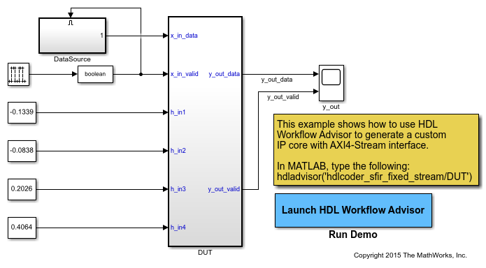
Open the model hdlcoder_sfir_fixed_stream. This model maps the
sfir_fixed model to the simplified AXI4-Stream protocol by
inserting the Valid signal as an input control
port.
openExample('hdlcoder_sfir_fixed_stream')
Open the HDL Workflow Advisor for the DUT subsystem. In the Set Target Device and Synthesis Tool task, specify
IP Core Generationas Target workflow and ZedBoard as Target platform. Click Run this task.In the Set Target Reference Design task, specify Default system with AXI4-Stream interface as the Target Reference Design. Click Run this task.
In the Set Target Interface task, map the DUT ports to target interfaces in the Target platform interface table. Click Run this task.

Right-click the Generate Software Interface task and select Run to selected task. Run the workflow to generate the software interface model.
The generated software interface model has the name
gm_hdlcoder_sfir_fixed_stream_interface.slx. Because your
original model uses scalar ports for the data ports x_in_data
and y_out_data, the Generate software
interface task displays a warning that AXI4-Stream IIO driver blocks
are not automatically generated in the software interface model. You can either
insert the driver blocks from the Embedded Coder Support Package Library for the target platform in the Simulink Library Browser or rerun the workflow by mapping the data ports to
vector signals. To see a software interface model that has the AXI4-Stream IIO
driver blocks inserted in it, open hdlcoder_sfir_fixed_stream_sw.
The model uses AXI4-Stream IIO
Write (Embedded Coder) and AXI4-Stream IIO Read (Embedded Coder) blocks for the data ports. The filter ports are
mapped to AXI4-Lite driver blocks.
Note
When your DUT uses half-precision and single-precision data types for AXI4 interfaces, you must replace the Data Type Conversion blocks in the generated software interface model with the Float Typecast block.
openExample('hdlcoder_sfir_fixed_stream_sw')
Configure the model with a stop time of inf. On the
Hardware tab, the hardware settings specified on the model.
You can then connect, and build and run the application on the target platform to
verify the HDL IP core functionality. See Generate IP Core with AXI-Stream Interface.