Design Considerations for Matrices and Vectors
These guidelines recommend how you can use matrix and vector signals when modeling your design for HDL code generation. Each guideline has a severity level that indicates the level of compliance requirements. To learn more, see HDL Modeling Guidelines Severity Levels.
Modeling Requirements for Matrices
Guideline ID
1.3.1
Severity
Mandatory
Description
HDL Coder™ support matrix data types at the DUT interfaces. You can use 2D or 3D matrices as an input to the DUT interface and generate HDL code for your model.
Example
This example shows how to use matrix types in HDL Coder. Open this model hdlcoder_matrix_multiply.
open_system('hdlcoder_matrix_multiply')
set_param('hdlcoder_matrix_multiply', 'SimulationCommand', 'update')
sim('hdlcoder_matrix_multiply')
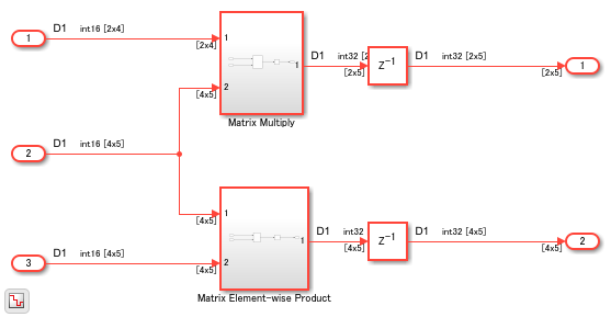
If you open the DUT Subsystem, you see two subsystems. One subsystem uses a Matrix Multiply block and the other subsystem performs element-wise multiplication.
open_system('hdlcoder_matrix_multiply/DUT')
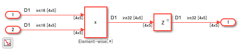
If you generate HDL code for the DUT Subsystem and open the generated model, you see how the multiplication operation is performed.
Modeling Considerations
When you use the Product block, use the right Multiplication mode. By using this mode, you can perform either matrix multiplication or element-wise multiplication. The multiplied output can have different dimensions depending on the Multiplication mode.
When you use the Product block to perform matrix multiplication, place the Matrix Multiply block inside a Subsystem block. When you generate code and open the generated model, you see that HDL Coder expands the matrix multiplication to multiple Product and Add blocks. Placing the Matrix Multiply block inside a subsystem makes the generated model easier to understand. In addition, make sure that you do not provide more than two inputs to the Matrix Multiply block.
Limitations
HDL code generation does not support matrix inputs in these HDL workflows:
Cosimulation model generation
FPGA-in-the-Loop
IP Core Generation
Avoid Generating Ascending Bit Order in HDL Code From Vector Signals
Guideline ID
1.3.2
Severity
Strongly Recommended
Description
In MATLAB®, the default bit ordering for arrays is ascending. The generated
VHDL code in such cases uses a declaration of std_logic_vector (0 to
n). This signal declaration generates warnings by violating
certain HDL coding standard rules. These are some scenarios:
Ascending Bit Order Scenarios
| Scenario | Problem Example | Workaround |
|---|---|---|
Delay
block with a Delay length greater
than | This example illustrates the generated code for a
Delay block with a Delay
length of
ENTITY Subsystem1 IS
  PORT( clk    :   IN   std_logic;
        reset  :   IN   std_logic;
        enb    :   IN   std_logic;
        In1    :   IN   std_logic;  -- ufix1
        Out1   :   OUT  std_logic   -- ufix1
        );
END Subsystem1;


ARCHITECTURE rtl OF Subsystem1 IS

  -- Signals
  SIGNAL Delay_reg   : std_logic_vector(0 TO 4);  -- ufix1 [5]
  SIGNAL Delay_out1  : std_logic;  -- ufix1
| Instead of using a Delay block with
a Delay length of
ENTITY Subsystem1 IS
  PORT( clk    :   IN    std_logic;
        reset  :   IN    std_logic;
        enb    :   IN    std_logic;
        In1    :   IN    std_logic;  -- ufix1
        Out1   :   OUT   std_logic  -- ufix1
        );
END Subsystem1;


ARCHITECTURE rtl OF Subsystem1 IS

  -- Signals
  SIGNAL Delay_out1    : std_logic;  -- ufix1
  SIGNAL Delay1_out1   : std_logic;  -- ufix1
  SIGNAL Delay2_out1   : std_logic;  -- ufix1
  SIGNAL Delay3_out1   : std_logic;  -- ufix1
  SIGNAL Delay4_out1   : std_logic;  -- ufix1
|
Combining multiple input signals to a vector signal using the Mux block. | This example illustrates the generated code when
you use a Mux block to combine
ENTITY Subsystem IS
  PORT( In1   :  IN   std_logic;  -- ufix1
        Out1  :  OUT  std_logic_vector(0 TO 3)  -- ufix1 [4]
        );
END Subsystem;


ARCHITECTURE rtl OF Subsystem IS

  -- Signals
  SIGNAL Mux_out1  : std_logic_vector(0 TO 3);  -- ufix1 [4]
| Use a Bit
Concat block to combine the input signals.
This example illustrates the generated code for this
block by concatenating ENTITY Subsystem IS
PORT( In1 : IN std_logic; -- ufix1
Out1 : OUT std_logic_vector(3 DOWNTO 0) -- ufix4
);
END Subsystem;
ARCHITECTURE rtl OF Subsystem IS
-- Signals
SIGNAL Bit_Concat_out1 : unsigned(3 DOWNTO 0); -- ufix4
|
Using a Constant block to generate vector signals. | This example illustrates the generated code when
you use a Constant
block to generate a vector of ENTITY Subsystem2 IS
PORT( Out1 : OUT std_logic_vector(0 TO 3) -- boolean [4]
);
END Subsystem;
ARCHITECTURE rtl OF Subsystem2 IS
-- Signals
SIGNAL Constant_out1 : std_logic_vector(0 TO 3); -- boolean [4]
| Use a Demux
block followed by a Bit
Concat block after the
Constant block. This example
illustrates the generated code when you apply this
modeling technique to the vector of ENTITY Subsystem2 IS
PORT( Out1 : OUT std_logic_vector(3 DOWNTO 0) -- ufix4
);
END Subsystem2;
ARCHITECTURE rtl OF Subsystem2 IS
-- Signals
SIGNAL Constant_out1 : std_logic_vector(0 TO 3); -- boolean [4]
SIGNAL Constant_out1_0 : std_logic;
SIGNAL Constant_out1_1 : std_logic;
SIGNAL Constant_out1_2 : std_logic;
SIGNAL Constant_out1_3 : std_logic;
SIGNAL Bit_Concat_out1 : unsigned(3 DOWNTO 0); -- ufix4
]
|