Hauptinhalt

plotCoverage

R2026b

Plot sensor beams and scan limits in trackingGlobeViewer

Description

plotCoverage(viewer,configs) plots the sensor beams and scan limits specified by the array of coverage configuration structures configs.

Note

When the CoverageMode property of the viewer is set to "Beam", the function plots only the sensor or emitter beam. When the CoverageMode property is set to "Coverage", the function plots the scan limits of the sensor.

plotCoverage(___,frame) specifies the reference frame used to interpret the Position field of the coverage configuration structures, in addition to the input arguments from the previous syntax.

example

plotCoverage(viewer,sensorData,sensorSpecs) plots the sensor coverages specified by the sensor data and sensor specification. (since R2026b)

Note

To plot sensor coverages using this syntax, set the CoverageMode property of the viewer to "Beam".

example

plotCoverage(___,Name=Value) specifies options using one or more name-value arguments. For example, plotCoverage(viewer,configs,Color=[1 0 0]) specifies the color of the plotted coverages as the RGB triplet [1 0 0].

example

Examples

collapse all

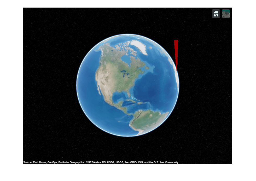
Create a tracking scenario, add a platform in the scenario, and mount a radar sensor on the platform.

scene = trackingScenario(IsEarthCentered=true);
r = fusionRadarSensor(1,RangeLimits=[0 5e6]);
radarTowerLLA = [10 10 1000];
platform(scene,'Position',radarTowerLLA,'Sensors',r);

Use the coverageConfig function to obtain the coverage configuration of the radar sensor.

covcon = coverageConfig(scene);

Create a tracking globe viewer and plot the coverage.

viewer = trackingGlobeViewer;
plotCoverage(viewer,covcon,"ECEF",Color=[1 0 0])

Take a snapshot and show the results.

drawnow
snapshot(viewer)
Create a tracking globe viewer and specify its reference location and camera position.

refloc = [42.39423231362 -70.95934958874 0];
mapViewer = trackingGlobeViewer('ReferenceLocation',refloc,'Basemap','streets-dark');
campos(mapViewer,refloc + [0 0 1e5]);

Load the sensor data and specifications for a monostatic radar and an ESM radar.

load("sensorDataFromTwoSensors.mat");

Plot coverages for both radars and specify the color for the detections from each sensor. Take a snapshot to show the results.

plotCoverage(mapViewer, {radar1Data,radar2Data}, ...
    {radar1Spec,radar2Spec},Color=[1 0 0; 0 1 0],Alpha=0.1)
drawnow
pause(20)
snapshot(mapViewer)
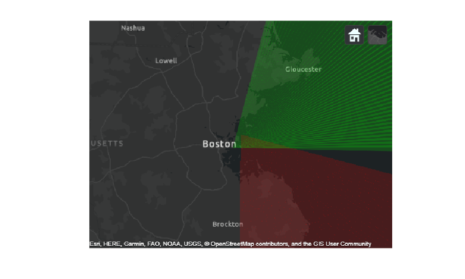
Figure contains an axes object. The hidden axes object contains an object of type image.

Additionally, you can plot the data of the radars using the plotSensorData function.

plotSensorData(mapViewer, {radar1Data,radar2Data}, ...
    {radar1Spec,radar2Spec},Color=[1 0 0; 0 1 0])
drawnow
snapshot(mapViewer)
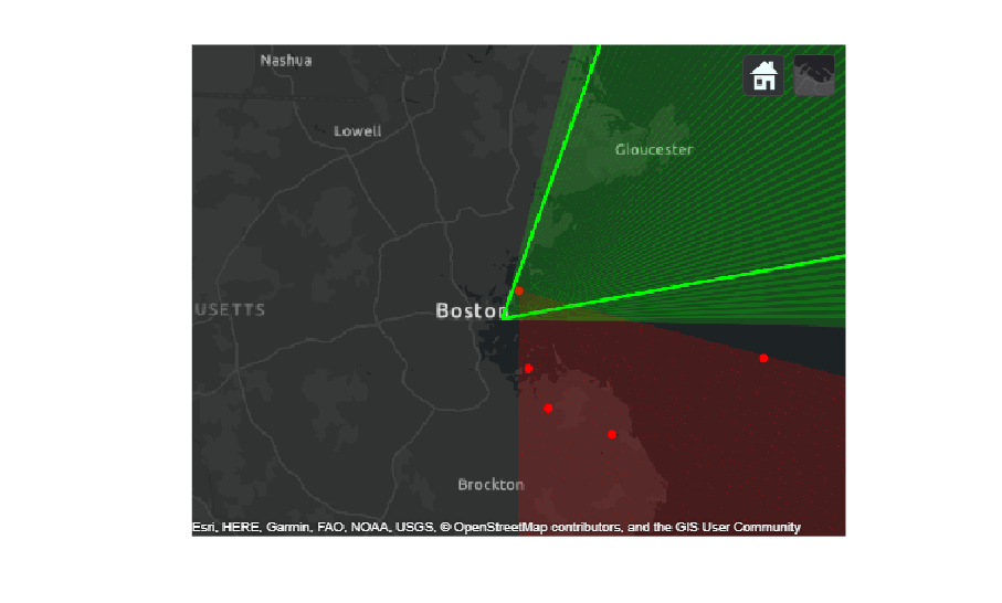
Figure contains an axes object. The hidden axes object contains an object of type image.

Input Arguments

collapse all

Tracking globe viewer, specified as a trackingGlobeViewer object.1

Coverage configurations, specified as an array of structures. Each structure contains these fields:

Fields of configurations

FieldDescription
Index A unique integer to identify sensors or emitters.
LookAngle

Current boresight angles of the sensor or emitter, specified as:

  • A scalar in degrees if scanning only in the azimuth direction.

  • A two-element vector [azimuth; elevation] in degrees if scanning in both the azimuth and elevation directions.

FieldOfViewField of view of the sensor or emitter, specified as a two-element vector [azimuth; elevation] in degrees.
ScanLimits

Minimum and maximum angles the sensor or emitter can scan from its Orientation.

  • If the sensor or emitter can only scan in the azimuth direction, specify the limits as a 1-by-2 row vector [minAz, maxAz] in degrees. The plotCoverage function then plots the field of view in the elevation dimension.

  • If the sensor or emitter can also scan in the elevation direction, specify the limits as a 2-by-2 matrix [minAz, maxAz; minEl, maxEl] in degrees.

RangeRange of the beam and coverage area of the sensor or emitter in meters.
PositionOrigin position of the sensor or emitter, specified as a three-element vector [X, Y, Z].
OrientationRotation transformation from the scenario or global frame to the sensor or emitter mounting frame, specified as a rotation matrix, a quaternion, or three Euler angles in ZYX sequence.

You can use the coverageConfig function to generate coverage configurations.

Note

Specify the Index field as a positive integer if the input is a sensor object, such as a fusionRadarSensor object. Specify the Index field as a negative integer if the input is an emitter object, such as a radarEmitter object.

Reference frame, specified as "NED" for north-east down, "ENU" for east-north-up, or "ECEF" for Earth-centered-Earth-fixed. When specified as "NED" or "ENU", the origin of the reference frame is at the location specified by the ReferenceLocation property of the viewer object.

Data Types: char | string

Since R2026b

Sensor data reported by each sensor, specified as a structure or a cell array of structures. The length and order of elements in the sensorData argument must match the length and order of sensor specifications in the sensorSpecs argument.

Since R2026b

Sensor specifications, specified as a sensor specification object or a cell array of sensor specification objects. The length and order of sensor specifications in the sensorSpecs argument must match the length and order of elements in the sensorData argument.

You can use the trackerSensorSpec function to generate sensor specification objects.

Name-Value Arguments

collapse all

Specify optional pairs of arguments as Name1=Value1,...,NameN=ValueN, where Name is the argument name and Value is the corresponding value. Name-value arguments must appear after other arguments, but the order of the pairs does not matter.

Example: plotCoverage(viewer,configs,Color=[1 0 0])

Color of sensor coverages, specified as:

  • "Auto" — Automatically select the color from a limited set of colors based on the Index field of each coverage configuration specified in the configs input.

  • An N-by-3 matrix of RGB triplets — Plot each coverage with a different color, where N is the number of sensor coverages specified in the configs input.

Coverage transparency, specified as a scalar in range [0, 1].

Version History

Introduced in R2021b

expand all


1 Alignment of boundaries and region labels are a presentation of the feature provided by the data vendors and do not imply endorsement by MathWorks®.