Interactively Configure C++ Interface
To streamline the integration of C++ code generated from Simulink® applications, components, and subsystems with external C or C++ code, configure a customized C++ class interface. When you generate C++ code from a model, the model appears as a class, the data elements appear as class members, and the model functions appear as class methods in the generated code. Configuring a C++ class interface enables you to customize the following aspects of the generated C++ code:
Class information — Class name and namespace
Class member information — Class member access and visibility
Class method information — Class method names and arguments
A customized C++ class interface enables the generated classes to meet specific code standards or interface requirements so that the generated code can compile and integrate into larger architectures with minimal post-generation customization.
Interactive Workflow Overview
The interactive workflow provides quick, intuitive, and complete configuration of a customized C++ class interface by using tools accessible directly from the C++ Code tab. From the tab, you can click Code Interface and access the Class Name & Namespace configuration dialog box and Code Mappings editor (with Property Inspector) to configure an interface.
To interactively configure a customized C++ interface:
Open Environment
Open the environment for configuring a customized C++ class interface:
Open the model
CppClassWorkflowKeyIgnition.openExample("CppClassWorkflowKeyIgnition")Open the Embedded Coder® app. In the Apps gallery, click Embedded Coder.
Set the language to C++. On the C++ Code tab, click Output and select Embedded C++ Code.

Set the model configuration parameters. To open the Configuration Parameters dialog box, on the C++ Code tab, click Settings, and select C/C++ Code generation settings. These parameters configure model-wide code generation behavior. To configure parameters specific to generating a customized C++ class interface, you can set these parameters (located on the Interface pane):
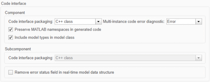
Configuration Parameter Description Code interface packaging (component) Specifies how function interfaces in generated code are packaged. For more information, see Code interface packaging (component). Multi-instance code error diagnostic Specifies the severity level for diagnostics displayed when a model violates requirements for generating multi-instance code. For more information, see Multi-instance code error diagnostic.
Include model types in model class Specifies to include model type definitions within the class namespace of the model. For more information, see Include model types in model class.
Code interface packaging (subcomponent) Specifies how model reference function interfaces in generated code are packaged. For more information, see Code interface packaging (subcomponent). Remove error status field in real-time model data structure Specifies whether to omit the error status field from the generated real-time model data structure
rtModel. For more information, see Remove error status field in real-time model data structure.Interface parameters that are related but are less commonly used appear under Advanced parameters.
Configuration Parameter Description Terminate function required Specifies whether to generate the
model_terminateCombine signal/state structures Specifies whether to combine global block signals and global state data into one data structure in the generated code. For more information, see Combine signal/state structures.
Generate destructor Specifies whether to generate a destructor for the C++ model class. For more information, see Generate destructor.
Use dynamic memory allocation for model block instantiation Specifies memory allocation for model hierarchies. For more information, see Use dynamic memory allocation for model block instantiation.
Configure Model as Class
Configure the class name and namespace. When you generate C++ code from a model, that model appears as a class in the generated code. To ease integration and comply with code and interface requirements, you can customize the generated class name. Optionally, you can scope the generated code and prevent symbol clashes within a project by specifying a namespace for the generated class. In modeled systems constructed as a model hierarchy, you can specify a different namespace for each model in the hierarchy.
The generated C++ class interface, declared in the model header file, incorporates the customized name and namespace:
// File: CppClassWorkflowKeyIgnition.h

namespace CustomizedNamespace
{
  class customized_ModelClass {
    // public data and function members
   public:

    // private data and function members
   private:

  };
}
Workflow
To configure the class name and namespace for a customized C++ class interface:
On the C++ Code tab, click Code Interface and select Class Name & Namespace.
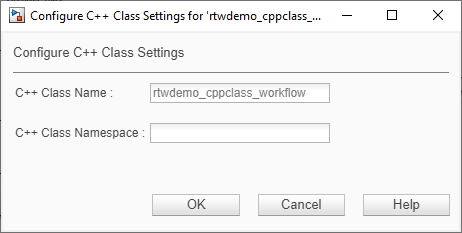
To configure the class name, edit the C++ Class Name field.
To configure the class namespace, edit the C++ Class Namespace field.
You can configure a nested namespace for the model by delimiting the namespaces by using the scope resolution operator
::in the formns1::ns2::ns3.Click OK. Validation is performed interactively with field warnings that alert you if you enter an invalid name or namespace.
Configure Model Data Elements as Class Members
Configure the visibility and access of class members. When you generate C++ code from a model, Simulink data elements appear as class members in the generated code. To adjust the encapsulation of the class data to meet code standards, security, or performance requirements, you can customize the visibility and access of the generated class members. Simulink data elements can be grouped into these categories of modeling elements:
| Model Element Category | Description |
|---|---|
| Inports | Root-level data input ports of a model, such as Inport and In Bus Element blocks. For more information, see Inport. |
| Outports | Root-level data output ports of a model, such as Outport and Out Bus Element blocks. For more information, see Outport. |
| Model parameter arguments | Workspace variables that appear as instance (nonstatic) class data members. |
| Model parameters | Workspace variables that are shared across instances of the model class and are generated as static class data members. |
| Signals, states, and internal data | Data elements that are internal to a model, such as block output signals, discrete block states, data stores, and zero-crossing signals. |
For each model element category, you can configure the data visibility to control the access modifier (access specifier) of the generated class members. Each option and its impact on the generated C++ class interface, declared in the model header file, is outlined in this table.
| Data Visibility Options | Description |
|---|---|
public | If you configure data elements as
File: CppClassWorkflowKeyIgnition.h

namespace CustomizedNamespace
{
  class customized_ModelClass {
   public:

    // example inport
    ExtU rtU;

    // example outport
    ExtY rtY;

    // example block signals and states
    DW rtDW;

    // Other data, methods, and types (not shown)
   private:
    …
  };
}
|
protected | If you configure data elements as File: CppClassWorkflowKeyIgnition.h
// Class declaration for model example_model
namespace CustomizedNamespace
{
class customized_ModelClass {
public:
protected:
// example inport
ExtU rtU;
// example outport
ExtY rtY;
// example block signals and states
DW rtDW;
// Other data, methods, and types (not shown)
private:
…
};
}
|
private | If you configure elements as File: CppClassWorkflowKeyIgnition.h
namespace CustomizedNamespace
{
class customized_ModelClass {
public:
private:
// example inport
ExtU rtU;
// example outport
ExtY rtY;
// example block signals and states
DW rtDW;
// Other data, methods, and types (not shown)
};
}
|
Individual arguments (Model parameter arguments
only) | If you configure model parameter arguments with visibility set to
The File: CppClassWorkflowKeyIgnition.h
namespace CustomizedNamespace
{
class customized_ModelClass {
public:
// model step function
void step1(real_T rty_engineState,
const real_T modelParameterArgument);
// Other data, methods, and types (not shown)
private:
…
};
}
|
After you set the data visibility of a model element category, you can configure the model access method to determine how the get and set methods are generated for the data elements. This configuration controls how application code can view and modify the class member data. Each option and its impact on the generated C++ class interface, declared in the model header file, is outlined in this table.
| Member Access Method Options | Description |
|---|---|
Method | If you configure inports as File: CppClassWorkflowKeyIgnition.h
namespace CustomizedNamespace
{
class customized_ModelClass {
public:
// example inport
void setInport(real_T localArgInput);
// example outport
real_T getOutport() const;
// example of model parameter arguments configured with
// ‘DataAccess’ ‘Direct'
real_T const &getInstP() const;
// example of model parameter arguments configured with
// ‘DataAccess’ ‘Pointer’
// real_T const *getInstP() const;
// example Block parameters get and set methods
const P &getBlockParameters() const;
void setBlockParameters(const P *pP) const;
// example Block states get and set methods
const DW &getDWork() const;
void setDWork(const DW *pDW);
private:
…
};
}
|
Inlined method | If you configure inports as File: CppClassWorkflowKeyIgnition.h
namespace CustomizedNamespace
{
class customized_ModelClass {
public:
// example inport set method
void setkeyState(real_T localArgInput) {
rtU.keyState = localArgInput;
}
// example outport get method
const real_T *getengineState() const {
return rtY.engineState;
}
// example Block parameters get and set method
const P &getBlockParameters() const {
return rtP;
}
void setBlockParameters(const P *pP) const {
rtP = *pP;
}
// example Block states get and set methods
const DW &getDWork() const {
return rtDW;
}
void setDWork(const DW *pDW) {
rtDW = *pDW;
}
private:
…
};
}
|
Structure-based method | If you configure the inports as File: CppClassWorkflowKeyIgnition.h
namespace CustomizedNamespace
{
class customized_ModelClass {
// public data and function members
public:
// External inputs (root inport signals with default storage)
struct ExtU {
real_T keyState; // '<Root>/keyState'
};
// External outputs (root outports fed by signals with default storage)
struct ExtY {
real_T engineState[3]; // '<Root>/engineState'
real_T cycleTime; // '<Root>/cycleTime'
};
…
// example inport
void setExternalInputs(const ExtU *pExtU);
// example outport
const ExtY &getExternalOutputs() const;
// Other model element categories may not be configured as ‘Structure-based method’
private:
…
};
}
|
Inlined structure-based method | If you configure the inports as File: CppClassWorkflowKeyIgnition.h
namespace CustomizedNamespace
{
class customized_ModelClass {
public:
// External inputs (root inport signals with default storage)
struct ExtU {
real_T keyState; // '<Root>/keyState'
};
// External outputs (root outports fed by signals with default storage)
struct ExtY {
real_T engineState[3]; // '<Root>/engineState'
real_T cycleTime; // '<Root>/cycleTime'
};
…
// example inport
void setExternalInputs(const ExtU *pExtU);
// example outport
const ExtY &getExternalOutputs() const;
// example inport
void setExternalInputs(const ExtU *pExtU)
{
rtU = *pExtU;
}
// example outport
const ExtY &getExternalOutputs() const
{
return rtY;
}
// Other model element categories may not be configured as ‘Inlined structure-based method’
private:
…
};
}
|
None | If you configure the access of a model element category as
File: CppClassWorkflowKeyIgnition.h

namespace CustomizedNamespace
{
  class customized_ModelClass {
   public:
   // External inputs (root inport signals with default storage)
   struct ExtU {
     real_T keyState;                   // '<Root>/keyState'
   };

   // External outputs (root outports fed by signals with default storage)
   struct ExtY {
     real_T engineState[3];             // '<Root>/engineState'
     real_T cycleTime;                  // '<Root>/cycleTime'
   };
    …

   // External inputs
   ExtU rtU;

   // External outputs
   ExtY rtY;

   private:
    …
  };
}
|
For each model element category, valid data visibility and member access method combinations are outlined in this table.
| Model Element Category | Data Visibility | Member Access Method |
|---|---|---|
| Inports | private | Method Inlined method Structure-based method Inlined structure-based method |
| protected | Method Inlined method Structure-based method Inlined structure-based method | |
| public | None Method Inlined method Structure-based method Inlined structure-based method | |
| Outports | private | Method Inlined method Structure-based method Inlined structure-based method |
| protected | Method Inlined method Structure-based method Inlined structure-based method | |
| public | None Method Inlined method Structure-based method Inlined structure-based method | |
| Model parameter arguments | Individual arguments | None |
| private | Method Inlined method | |
| Model parameters | private | None Method Inlined method |
| protected | None Method Inlined method | |
| public | None Method Inlined method | |
| Signals, states, and internal data | private | None Method Inlined method |
| protected | None Method Inlined method | |
| public | None Method Inlined method |
For model parameter arguments, you can configure block parameters to be
instance-specific or shared when the visibility is private. See
Configure Parameters for C++ Interface Code Generation for more information.
To configure Individual arguments visibility for model
parameter arguments, the model must be a referenced model. Only referenced models can
generate methods that use individual arguments.
For inports, outports, and model parameter arguments, you can additionally specify
whether the data for the model element category is stored by value
('Direct') or pointer ('Pointer') in the generated
code.
When configuring data access for Inports or
Outports as pointer members, the model must have model
configuration parameters set to either generate an example ERT main program
(ert_main.cpp) or generate code only. Additionally, the data access
method for the inports or outports must be structure-based. To configure the data access
method for model parameter arguments, data visibility cannot be set to
Individual arguments.
Workflow
To configure the class members of a customized C++ class interface:
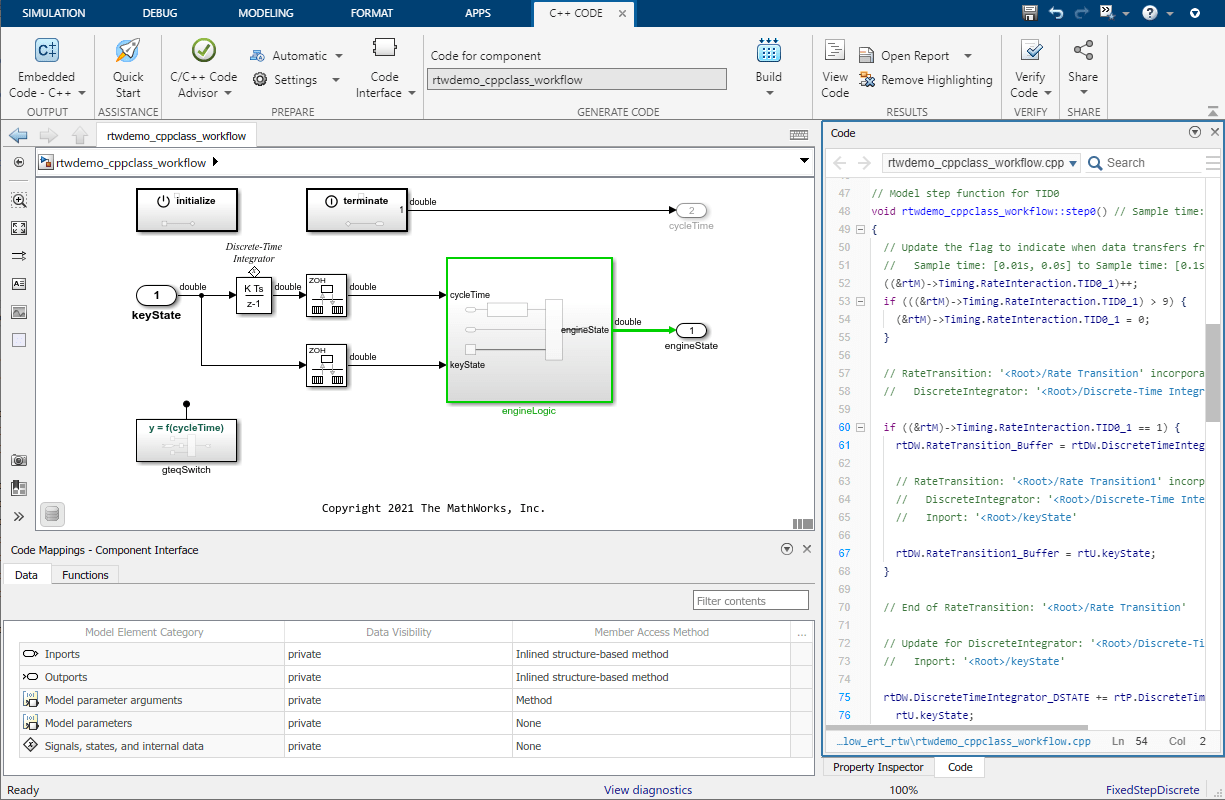
Open the Code Mappings editor. On the C++ Code tab, click Code Interface and select Code Mappings.
Open the Data pane. In the Code Mappings editor, click the Data tab.

Configure the visibility. To configure the visibility of a category of Simulink data elements in the generated code, from the Data Visibility column, select an access specifier from the given options. Options vary depending on the Model Element Category.
Configure the member access. To configure the access of a category of Simulink data elements in the generated code, from the Member Access Method column, select how to generate get and set methods from the given options. Options vary depending on the Model Element Category and the selected Data Visibility.
Configure the data access. To configure data access for inports, outports, or model parameter arguments:
Select the model element that you want to configure (Inports, Outports, or Model parameter arguments).
Verify that Data Visibility and Member Access Method are set as needed to configure data access.
Data access is configurable for inports, outports, and model parameter arguments with these specifications:
'Inports'whose member access method is set to'Structure-based method'or'Inlined structure-based method'.'Outports'whose member access method is set to'Structure-based method'or'Inlined structure-based method'.'ModelParameterArguments'whose data visibility is set to'private'(not'Individual Arguments').
Click
 to open the Data Access
dialogue box, and select
to open the Data Access
dialogue box, and select PointerorDirect.
Configure Model Functions as Class Methods
Configure the class method names and arguments. When you generate C++ code from a model, model functions appear as class methods in the generated code. To integrate with external code or interface requirements, you can customize the name of the generated class methods. Additionally, for base-rate periodic functions and Simulink Functions, you can configure the name, order, and identifier of the generated arguments.
The generated class methods are referred to as entry-point methods and are locations in code where a transfer of program control (execution) occurs. Entry-point methods vary depending on the type of Simulink model and can be grouped into the following types:
| Model Type | Type of Model Function | Description | Name of Model Function | Expected Method Name |
|---|---|---|---|---|
| Export-Function Models | Exported function | The exported function for a subsystem. | ExportedFunction:,
where | |
| Simulink Function | The exported function for a Simulink Function block. | Simulink
Function: where
| | |
| Export-Function or Rate-based Models | Initialize function | Initialization code for a model. At the start of the application
code, call the function once. Do not use this function to
reset the real-time model data structure
( | Initialize | |
| Partition function | For a model partition, output and update code. Model configuration parameter Single output/update function is selected (the default). | Partition:, where
| | |
| Periodic multitasking function | For blocks in a rate-based model configured for multitasking, output and update code. The code generator produces a function for each sample period. Model configuration parameter Single output/update function is selected (the default). | Periodic: where
| | |
| Periodic single-tasking function | For blocks in a rate-based model configured for single-tasking, output and update code. Model configuration parameter Single output/update function is selected (the default). | Periodic | | |
| Reset function | If the model includes a Reset Function block, reset code generated. To reset conditions or state, call the function from the application code. | Reset: where
| | |
| Terminate function | Code for turning off a system. For ERT-based models, you can suppress generation of this function by clearing the model configuration parameter Terminate function required (set by default). | Terminate | |
The generated C++ class interface, declared in the model header file, incorporates the function name and argument customizations in the generated entry-point methods:
File: CppClassWorkflowKeyIgnition.h

namespace CustomizedNamespace
{
  class customized_ModelClass {
   public:
    // model initialize function- customized name
   void customized_initialize();

    // model step function- customized name & arguments
   void customized_step(customArg1, const* customArg2);

    // model terminate function- customized name
   void customized_terminate();

    // Constructor
   customized_ModelClass();

    // Destructor
   ~customized_ModelClass();

   private:
  …
  };
}
Workflow
Open the Code Mappings editor. On the C++ Code tab, click Code Interface and select Code Mappings.
Open the Functions pane. In the Code Mappings editor, click the Functions tab. To view a complete list of entry-point functions for your model, click the Update Diagram button.
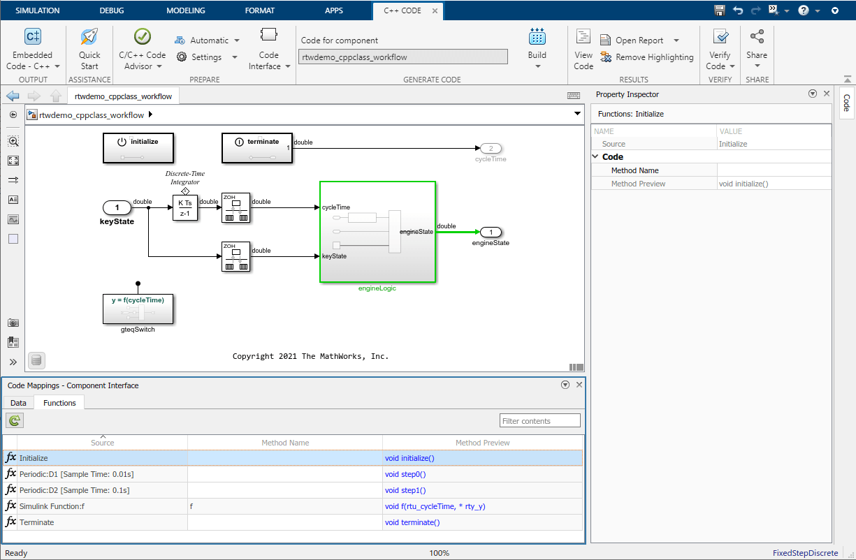
Configure method names.
To configure the name of an entry-point method in the generated code, from the Method Name column, click and directly edit the spreadsheet. You can enter a custom name or you can use identifier format parameters to control a dynamically generated name. For more information about identifier format parameters, see Identifier Format Control.
Verify the name in the Method Preview column.
Configure method arguments. For base-rate periodic functions and Simulink Functions, you can configure the name, order, and identifiers of the method arguments.
To configure the arguments of a base-rate periodic function:
Open the Step Function Interface configuration dialog box. From the Code Mappings editor, on the Functions tab, in the Method Preview column, click the method preview hyperlink of a base-rate periodic function:
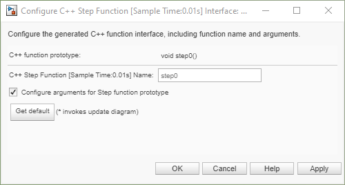
In the dialog box, select Configure arguments for Step function prototype and click Get default. This action launches a view of the method arguments.

To change the order of the arguments, click and drag the argument rows in the viewer.
To change the identifier, in the C++ Type Qualifier column, select the appropriate identifier from the drop-down list:
Identifier Option Preview Value (Inports only) myPeriodicFunction(argInport) Const Reference (Inports only) myPeriodicFunction(const & argInport) Pointer to Const myPeriodicFunction(const * argInport) Pointer myPeriodicFunction(* argInport) Const Pointer to const myPeriodicFunction(const * const argInport) To change the name of an argument, in the C++ Identifier Name column, click and directly edit the name. You can enter a custom name or you can use identifier format parameters to control a dynamically generated name. For more information about identifier format parameters, see Identifier Format Control.
If you enter the same name for an inport argument and an outport argument the inport and outport appear as one parameter in the generated method. For example, if you specify an inport as
argInportand an outport argument asargOutport, the generated method would be:myStepFunction(argInport, argOutport);
If you specify an inport argument as
argIOand an outport argument asargIO, the generated method would be:myStepFunction(argIO);
To verify the arguments selections, click Validate.
To apply changes and exit the dialog box, click OK.
To configure the arguments of a Simulink Function:
Open the Simulink Function Interface configuration dialog box. From the Code Mappings editor, on the Functions tab, in the Method Preview column, click the method preview hyperlink of a Simulink Function:
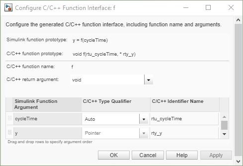
To change the return argument, select a return argument option from the C/C++ return argument drop-down list.
To change the order of the arguments, click and drag the argument rows in the viewer.
To change the identifier, in the C++ Type Qualifier column, select the identifier from the drop-down list:
Identifier Option Preview Auto mySimulinkFunction(argInport) Const Reference (Inports only) mySimulinkFunction(const & argInport) Reference mySimulinkFunction(& argOutport) Pointer to Const mySimulinkFunction(const * argInport) Pointer mySimulinkFunction(* argInport) Const Pointer to const mySimulinkFunction(const * const argInport) To change the name of the argument, in the C++ Identifier name column, click and directly edit the name. You can enter a custom name or you can use identifier format parameters to control a dynamically generated name. For more information about identifier format parameters, see Identifier Format Control.
To verify changes to the Simulink Function arguments, review the Simulink function prototype field to view the expected method prototype.
To apply changes and exit the dialog box, click OK.
Generate C++ Class Interface
Generate the customized C++ class interface by generating code from the model. To verify your C++ class interface configurations, build the model and view the generated class, class member, and class method representations.
Generate code. To generate a C++ class interface, on the C++ Code tab, click Build.
View code. To view the generated code, on the tab click View Code. The generated code appears beside the model in the model workspace.
Iterate. If the generated interface does not meet code requirements, make configuration adjustments until requirements are satisfied.
If the generated code representation does not meet your requirements, reconfigure the interface and generate code again until code generations requirements are satisfied. For guidance on understanding the generated code, see Analyze Generated Data Code Interface Report.
Considerations and Limitations
Instance-Specific Parameter Support — You can use model parameter arguments to configure workspace variables that have been specified as arguments. You can configure these arguments as private members of your class or as individual arguments defined outside the class. To configure within the class, you can set the data visibility to private and configure the generation of the get and set methods. Optionally, you can configure the class member values as defined within the class (in the Property Inspector, set Data Access to
Direct) or passed-by-reference through the class constructor (in the Property Inspector, set Data Access toPointer). The data access setting is supported for top model builds. For reference model builds, the code is generated as references in the model class. To configure instance-specific parameters outside the class, set the data visibility to Individual arguments.Instance-specific parameter limitations include:
MATLAB® variables marked as model arguments are not able to be configured as private class members.
Model parameter arguments are not supported by right-click builds.
Interface Code Generation Behavior — The I/O arguments style of step method specification supports single-rate models and multirate single-tasking models. Multirate multitasking models are not supported. Additionally, the C++ encapsulation interface is not the default, the value is ignored for the Pass fixed-size scalar root inputs by value for code generation parameter.
Stateflow® considerations — If you have a Stateflow license, for a Stateflow chart that resides in a root model configured to use the
I/O arguments step methodfunction specification, and that uses a model root inport value or calls a subsystem that uses a model root inport value, do one of the following to generate code:In the Stateflow chart, clear the Execute (enter) Chart At Initialization check box.
Insert a Simulink Signal Conversion block immediately after the root inport. In the Signal Conversion block parameters dialog box, select Exclude this block from 'Block reduction' optimization.
Simscape™ Considerations — If a model root inport value connects to a Simscape block, insert a Simulink Signal Conversion block between the root inport and the Simscape conversion block. In the Signal Conversion block parameters dialog box, select Exclude this block from 'Block reduction' optimization.
Referenced Model Considerations — When building a referenced model that is configured to generate a C++ class interface:
Do not use a C++ class interface in cases when a referenced model cannot have a combined output/update function. Cases include a model that has a continuous sample time or saves states.
Do not use virtual buses as inputs or outputs to the referenced model when the referenced model uses the I/O arguments step method. When bus signals cross referenced model boundaries, either use nonvirtual buses or use the Default step method.