Service Interfaces
When generating C code from a top model for application deployment, you map model data elements to storage classes. A storage class specifies the appearance and placement of data elements in the generated code. Storage classes apply direct-access data communication. The list of storage classes available for mapping is determined by the Embedded Coder® Dictionary that is associated with the model. The dictionary can define default settings, which can simplify the mapping process when the default mappings apply for your model.
When generating code from a component model that uses a C service code interface configuration, you map model data elements to service interfaces. A service interface specifies function prototype information and a data communication method (direct-access, outside-execution, or during-execution) for the generated code as required by the target platform services. The code generator applies constraints when producing service interface code so that it is easier to integrate the code for use in a specific target environment. The list of service interfaces available for mapping is determined by interfaces defined in the shared Embedded Coder Dictionary that is attached to the model. If dictionary default service interfaces align with your target platform service requirements, you need not make mapping changes and can skip to generating and reviewing the component interface code.
Tip
If you need to set up a component model to use a data code interface configuration, see the Component Deployment Guidelines for Embedded Coder Support Package.
Before R2026a, data elements in models with service interface configuration could only
resolve to signal objects with Auto storage class. Since R2026a you
can apply direct-access data communication by resolving signals to signal objects with
non-Auto storage class. These model elements can resolve to signal
objects with non-Auto storage class:
Root-level inports and outports
Signals
States
Data stores
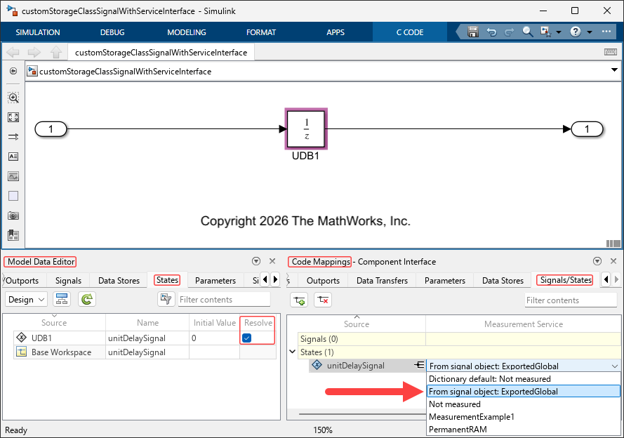
When you resolve a model element to a signal object with a storage class other
than Auto, the Sender Service,
Receiver Service, or Measurement Service of the
element is automatically set in the code mappings to From signal object:
, where storage classstorage
classExportedGlobal
storage class. The Measurement Service of the block is specified in the
code mappings as From signal object: ExportedGlobal.
Note
Depending on the model deployment type, some elements are hidden from the Code
Mappings editor. However, both visible and hidden elements are mapped to
From signal object:
when they are resolved to signal objects with storage classes other than
storage classAuto.
Receiver and Sender Service Interfaces
Within a target environment, a component receives data from and sends data to other components by calling the target platform receiver and sender services. To represent calls to the receiver and sender services in a component model and configure the relevant data elements for code generation:
In the component model:
Represent a data receive request by using a root-level inport (In Bus Element or Inport block).
Represent a data send request by using a root-level outport (Out Bus Element or Outport block).
Configure your model to use a shared Embedded Coder Dictionary that defines a service code interface configuration and open the Embedded Coder app.
Select Code Interface > Component Interface.
In the Code Mappings editor, on the Inports and Outports tabs, inspect the mapping for each root-level inport and outport. If you need to use a service other than the default, select an alternative. For example, a service interface might be available for each data communication method.
Save your interface configuration changes by saving the model.
If you prefer, you can map the root-level inports and outports to receiver and sender
service interfaces by using the code mappings programming interface. See coder.mapping.api.CodeMapping.
A best practice is to represent communication I/O ports at the root-level of an application or component model by using In Bus Element and Out Bus Element blocks.
As a named signal interface, these blocks reduce wiring in the model and avoid issues with port reordering.
As a structured data type, these blocks enable use of arrays of buses.
To represent a bus as a signal interface, use an In Bus Element or
Out Bus Element block that has the Bus virtuality
attribute set to virtual. Virtual buses provide a way to group
signals so that you can access them as a whole or select specific signals. A virtual bus
consisting of one signal is equivalent to using an Inport or
Outport block.
To enforce the composition of a bus interface, use a bus object. A bus object specifies the architectural properties of a bus, such as element names, hierarchy, order, and data types. A bus object is analogous to a structure definition in C. The object defines members of the bus but does not create the bus.
To reduce the number of function arguments that are passed to a reference model in the generated code, choose one of these options for configuring an In Bus Element:
Set the block Bus virtuality attribute to
nonvirtualand, in the model code mappings, for the inport, set the storage class.Set the block Bus virtuality attribute to
virtualorinheritedand, in the model code mappings, for the inport, set the storage class toDefault.
If you have a requirement to represent root-level I/O in the generated code as a
structured data type, model the inport or outport as a nonvirtual bus. The data type of a
nonvirtual bus must be a Simulink.Bus object that is defined in the model
base workspace or data dictionary.
Note
For an export-function model, you cannot configure a root-level inport or outport to use a service interface if the port is connected to a signal that is configured with a storage class.
For an example, see Generate Sender and Receiver C Interface Code for Component Deployment.
For more information, see:
Data Transfer Service Interfaces
Within a target environment, a component transfers data between callable functions by calling the target platform data transfer service. The callable functions are entry-point functions that target environment software can call. To represent calls to a platform data transfer service and configure the relevant data elements for code generation:
In the component model, represent a data transfer by using a signal line to connect two blocks that exchange data and result in callable entry-point functions in generated code.
Configure your model to use a shared Embedded Coder Dictionary that defines a service code interface configuration and open the Embedded Coder app.
Select Code Interface > Component Interface.
In the Code Mappings editor, on the Data Transfers tab, inspect the mapping for data transfer signals. If you need to use a service other than the default, select an alternative. For example, a service interface might be available for each data communication method.
Save your interface configuration changes by saving the model.
If you prefer, you can map the signal lines that represent data transfers to data transfer
service interfaces by using the code mappings programming interface. See coder.mapping.api.CodeMapping.
For an example, see Generate C Data Transfer Service Interface Code for Component Deployment.
For more information, see:
Nonvolatile Memory Interfaces
You can choose between several approaches to model interfacing for target environment nonvolatile memory. You can use a measurement service interface for persistent data, I/O ports with initialize and terminate functions, or a client-server interface.
| Requirement | Measurement Service Interface for Persistent Data | I/O Ports with Initialize and Terminate Functions | Client-Server Interface |
|---|---|---|---|
| Robust handling of memory access by functions that execute concurrently | X | X | |
| Multiple instances of a component | X | X | |
| Use target platform service | X | X | |
| Support asynchronous read/write to nonvolatile memory | X |
Measurement Service Interface for Persistent Data
Internal state and data store data can be stored in nonvolatile memory and managed by an external memory management service. Using a measurement service interface for persistent data supports robust, synchronous or asynchronous handling of the memory accesses.
To configure your nonvolatile memory interface by using the measurement service interface for persistent data:
Configure your model to use a shared Embedded Coder Dictionary that defines a measurement service interface configuration for persistent data and open the Embedded Coder app.
Select Code Interface > Component Interface.
In the Code Mappings editor, on the Data Stores and Signals/States tabs, configure the code interfaces for data store and state variables that are used for persistent memory. Map the data store and state variables to a measurement service interface that has persistent memory enabled and uses a storage type that specifies that data is not be initialized in the generated code, allowing an external nonvolatile memory service to initialize the data.
Save your interface configuration changes by saving the model.
For more information, see:
I/O Ports with Initialize and Terminate Functions
For robust handling of synchronous memory accesses by functions that execute concurrently or if you are using multiple instances of a component, model and configure your nonvolatile memory interface as follows:
In the component model:
Represent a direct memory read with an inport (Inport or In Bus Element block) connected to an Initialize Function block.
Represent a direct memory write with an outport (Outport or Out Bus Element block) connected to a Terminate Function block.
Configure your model to use a shared Embedded Coder Dictionary that defines a service code interface configuration and open the Embedded Coder app.
Select Code Interface > Component Interface.
In the Code Mappings editor, configure the code interfaces for the Inport and Outport blocks that are connected to the Initialize Function and Terminate Function blocks. Map the Inport and Outport blocks to a service interface that uses the direct-access data communication method.
Alternatively, (since R2026a) you can resolve the Inport and Outport block signals to
Simulink.Signalobjects with non-Autostorage classes, and specify their Sender Service and Receiver Service asFrom signal object:, wherestorage classstorage classis the storage class of theSimulink.Signalobject (for exampleFrom signal object: ExportedGlobal).In the Code Mappings editor, on the Functions tab, inspect the mapping for each initialize and terminate entry-point function. If necessary, adjust the default function prototypes. For more information, see Configure Generated C Function Interface for Model Entry-Point Functions.
Save your interface configuration changes by saving the model.
For more information, see:
Client-Server Interface
Use a centralized client-server interface to access the nonvolatile memory of a target environment when the target environment provides a platform service. To use the client-server approach:
In the model:
Represent the target environment service that provides access to nonvolatile memory by using a Simulink Function block.
Access the service by using a Function Caller block.
If you have not already done so, configure your model to use a shared Embedded Coder Dictionary that defines a service code interface configuration and open the Embedded Coder app.
Configure the function prototype generated for the blocks to align with target platform requirements by using the Code Mappings editor. See Configure C Entry-Point Function Interfaces for Simulink Function and Function Caller Blocks.
Save your interface configuration changes by saving the model.
For more information, see:
Timer Service Interfaces
For component model functions, you can generate code that accesses the function clock tick used by the target environment. A function clock tick value is the number of time ticks from the start of program execution to the present time for a function. Generated code for a function can access the target platform function clock tick value by calling a function provided by the platform timer service.
You can configure and generate a call to a timer service function for:
Aperiodic entry-point functions generated from models that use blocks that rely on an elapsed time value (Discrete-Time Integrator and Weighted Sample Time blocks).
Periodic entry-point functions generated from models that use blocks that rely on elapsed time in an aperiodic context. An example of an aperiodic context is when the Sample time type parameter of the Trigger Port block of the model or subsystem that includes the time-based block is set to
triggered.Periodic entry-point functions generated from models that use blocks that rely on absolute time values, such as Sine Wave and Pulse Generator blocks.
You represent requests for the function clock tick in a model implicitly when you include blocks that rely on elapsed or absolute time values. To configure the code generator to produce code that calls a timer service function, use the Code Mappings editor or code mappings programming interface to map functions that use time-based blocks to a timer service interface defined in the Embedded Coder Dictionary that is configured for the model.
The code generator assumes that:
The target platform timer service maintains integrity of the function clock tick value, including during concurrent access, for single- and multiprocess target environments and supports the outside-execution and during-execution data communication methods.
The clock resolution is specified in seconds with model configuration parameter Clock resolution (
ClockResolution). If Clock resolution is set to-1, the clock resolution is inherited based on scheduling properties for the model style and type of function (periodic or aperiodic). For example, the code generator sets the inherited clock resolution for an aperiodic function to the model fixed-step size (fundamental sample time). For periodic functions, the inherited clock resolution is the function sample time.
This timing diagram shows how the function clock tick service for a target platform communicates data by using the outside-execution and during-execution data communication methods.
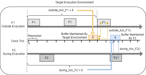
In the diagram, functions F1 and F2 represent
generated callable functions that are configured to interface with timer service functions.
F1, the faster of the two functions, is configured to interface with
service function outside_tick_F1, which uses outside-execution data
access. Before F1 executes, the service function writes clock tick value
eight to a buffer that the target environment maintains. The service holds that value constant
until execution of F1 is complete. The diagram shows
F1 accessing the clock tick value twice by calling
outside_tick_F1. Each function call returns the tick value
eight.
F2 is configured to interface with service function
during_tick_F2, which uses during-execution data access. Function
during_tick_F2 returns the current clock tick value at the time of the
service call. When the model uses during-execution data access, the timer service does not
save the value in a locked buffer. The value that the service function returns can change as
the F2 executes. To maintain data coherency, the first time that
F2 calls service function during_tick_task2,
F2 creates a buffer to store clock tick value nine and locks it.
Subsequent calls to during_tick_F2 access the tick value from the locked
buffer maintained by the F2. The diagram shows a second call to the service function, which
returns tick value nine.
To represent calls to a platform timer service and configure the relevant data elements for code generation:
In the component model, add blocks that rely on time as needed.
Configure your model to use a shared Embedded Coder Dictionary that defines a service code interface configuration and open the Embedded Coder app.
Select Code Interface > Component Interface.
In the Code Mappings editor, on the Functions tab, inspect the timer service mappings component model functions. Select the row for a function. Click the pencil icon
 . In the dialog box that appears, check the setting of the
Timer Service property. If you need to use a service interface
other than the default, set the property to the name of the required timer service
interface. For example, a service interface might be available for each data communication
method.
. In the dialog box that appears, check the setting of the
Timer Service property. If you need to use a service interface
other than the default, set the property to the name of the required timer service
interface. For example, a service interface might be available for each data communication
method.Save your interface configuration changes by saving the model.
If you prefer, you can associate a timer service interface with an entry-point function by
using the code mappings programming interface. See coder.mapping.api.CodeMapping.
For an example, see Generate C Timer Service Interface Code for Component Deployment.
For more information, see:
Parameter and Parameter Argument Tuning Service Interfaces
Some components require interface support for tunable parameters and parameter arguments. When a parameter or parameter argument is tunable, you can change the value that is stored in memory during program execution. For example, you can use a tunable parameter to determine an optimal value by changing the value and monitoring the results or to adapt an algorithm to different execution conditions. An example of a block parameter value that you might want to be tunable is the Gain parameter of the Gain block.
To represent a parameter or parameter argument in a component model and configure the parameter to be tunable in generated code:
Set up the parameter data for the model by defining the data as a parameter object in the model workspace. For parameter argument data, select the Argument property.
Configure your model to use a shared Embedded Coder Dictionary that defines a service code interface configuration and open the Embedded Coder app.
Select Code Interface > Component Interface.
In the Code Mappings editor, on the Parameters tab, inspect the parameter mappings. If you need to use a service other than the default, change the service setting. If you do not need to tune a parameter, select
Not tunable.Optionally, for each parameter and parameter argument that you want to tune, you can specify an identifier that informs the code generator how to represent the variable in the generated code. In the row for a parameter or parameter argument, select the pencil icon
. In the dialog box that appears, specify a value for the
Identifier property.Save your interface configuration changes by saving the model.
If you prefer, you can map parameters and parameter arguments to parameter tuning and
parameter argument tuning service interfaces, by using the code mappings programming
interface. See coder.mapping.api.CodeMapping.
After you configure parameter and parameter argument interfaces, you can:
Set up and run external mode simulations that use a communication channel between Simulink® on your development computer (host) and your generated executable program that runs on the target platform by using the Run on Custom Hardware app.
Generate and customize an ASAP2 file and a Calibration Data Format (CDF) file by using the Generate Calibration Files tool.
Use the C application programming interface (API) or Target Language Compiler (TLC) programming interface to tune parameters and parameter arguments.
For an example, see Generate C Parameter Tuning Service Interface Code for Component Deployment.
For more information, see:
Measurement Service Interfaces
Some components require interface support for viewing and analyzing model data (signal, state, and datastore data) during program execution. For example, you can use the Simulation Data Inspector to produce plots and maps of the data for comparing run results that show model behavior.
To represent model data in a component model and configure the data elements for measurement in generated code:
Set up the data elements in the model design.
Data Element Representation in Model Signal Output port of block State State on block Datastore Datastore Memory block Configure your model to use a shared Embedded Coder Dictionary that defines a service code interface configuration and open the Embedded Coder app.
In the Embedded Coder app, open the Code Mappings editor. In the C Code tab, select Code Interface > Individual Code Mappings.
For signals, add the signal lines that you want to measure to the model code mappings.
In the component model, select a signal.
Pause on the ellipsis that appears above or below the signal line to open the action bar. Click the Add Signal button.
In the Code Mappings editor, on the Signals/States tab, the Signals node expands and lists the signal that you added.
If you need to use a service interface other than the dictionary default for measurement data:
On the Signals/States tab, select an alternative measurement service for a selected signal or state. For signals and states that you do not want to measure, select
Not measurable.On the Data Stores tab, select an alternative measurement service for a selected data store. For data stores that you do not want to measure, select
Not measurable.
For each signal and state, select the pencil icon
. In the dialog box that appears, specify a value for the
Identifier property. The identifier informs the code generator how
to represent the variable in the generated code.Save your interface configuration changes by saving the model.
If you prefer, you can map signals, states, and datastores to measurement service
interfaces, by using the code mappings programming interface. See coder.mapping.api.CodeMapping.
After you configure measurement interfaces, you can:
Set up and run external mode simulations that use a communication channel between Simulink on your development computer (host) and your generated executable program that runs on the target platform by using the Run on Custom Hardware app.
Generate and customize an ASAP2 file and a Calibration Data Format (CDF) file by using the Generate Calibration Files tool.
Use the C application programming interface (API) or Target Language Compiler (TLC) programming interface to visualize and analyze signal, state, and data store data without using external mode.
For an example, see Generate C Measurement Service Interface Code for Component Deployment.
For more information, see:
Service Interface Constraints
When designing and configuring a component model that uses a service code interface configuration, consider constraints that the code generator applies and release-specific limitations.
Service interface constraints are product features that are not relevant and are not supported when you are deploying software that uses a service interface configuration.
Modeling styles and patterns that are not supported:
Blocks that use continuous state
Message Triggered Subsystem blocks
S-function blocks that specify option
SS_OPTION_ASYNCHRONOUS,SS_OPTION_ASYNCHRONOUS_INTERRUPT, orSS_OPTION_ASYNCHRONOUS_CUSTOMto change slower task IDs to faster task IDsS-function outports that have a mix of data and function-call elements
Use of state ports
Classicinitialization mode for conditionally executed subsystem initialization valuesGlobal datastores
Multirate enabled subsystems
Multirate S-functions
Model configuration constraints:
Cannot select Support continuous time (
SupportContinuousTime)Cannot specify external model for parameter tuning and signal monitoring by using XCP transport layer
Cannot select Generate an example main program (
GenerateSampleERTMain)Cannot select MAT-file logging (
MATFileLogging)Must select Remove root level I/O zero initialization (
ZeroExternalMemoryAtStartup='off')Cannot select Target supports function prototype control (
ModelStepFunctionPrototypeControlCompliant)Cannot specify TLC options (
TLCOptions) --aInlineSetEventsForThisBaseRateFcn=TLC_FALSE,-aSuppressMultiTaskScheduler=TLC_FALSE,-aRateBasedStepFcn=TLCFALSE, -(wrapper function)
Receiver and sender service interface constraints:
Export-function models that include a signal that is configured with a storage class and is connected to a root-level inport or outport
Other capabilities that are not supported:
Function prototype control for Initialize Function, Reset Function, and Terminate Function blocks, component step functions, and private Simulink Function blocks
Automatic switching between simulation and code generation variants
Subsystem builds
Use of external mode for parameter tuning and signal monitoring
Preserving dimensions of multidimensional arrays when they are accessed by target environment service functions called by generated service interface code
Service Interface Limitations
These limitations apply when you deploy software that uses a service interface configuration.
Modeling patterns that are not supported:
Partitioned multirate rate-based models
Subsystem Reference and Reinitialize Function blocks
Rate Transition blocks in export-function models
Use of function ports to call Simulink functions in a reference model from another reference model
Use of State Reader and State Writer blocks connected to outports or used in functions other than initialize, reset, or terminate functions
Message-based communication involving signal connections between root-level inports and outports and between Send and Receive blocks
Global datastores and local datastores that are configured with a global storage class, such as
ExportedGlobalSimulink Function blocks that have the Function visibility parameter set to
globalComponent models that have model configuration parameter Code interface packaging set to
Reusable
            function
Model configuration limitations:
Cannot set Language (
TargetLang) toC++and Code interface packaging (CodeInterfacePackaging) toC++ classCannot set Code interface packaging (
CodeInterfacePackaging) toReusable function
Service Interface Limitations Removed
These capabilities remove limitations from software that uses a service interface configuration.
The diagnostic parameter Multitask data store is enabled. (since R2026a)
You can select Support variable-size signals (
SupportVariableSizeSignals). (since R2026a)You can specify the
Reusable
            function
setting of the Code interface packaging (Code interface packaging) configuration parameter. (since R2025a)You can select the Support non-inlined S-functions (
SupportNonInlinedSFcns) configuration parameter. (since R2024b)You can select the Single output/update function (
CombineOutputUpdateFcns) configuration parameter. (since R2024b)You can select the Invalid input data access in chart initialization (
SFInvalidInputDataAccessInChartInitDiag) parameter. (since R2024b)You can clear the Combine signal/state structures (
CombineSignalStateStructs) configuration parameter. (since R2024b)You can set the Default parameter behavior (
DefaultParameterBehavior) totunable. (since R2024b)You can set the Classic call interface (
GRTInterface). (since R2024a)Multirate, rate-based models are supported except when they are partitioned. (since R2024a)
You can have component models with root-level Inport blocks meeting the following conditions:
The Inport block is mapped to a receiver service interface with the data communication method set to
During
                  Execution
. (since R2024a)One branch of the Inport block is driving a subsystem whose function interface is not set to Allow arguments (Match graphical interface). (since R2024a)
Rate transition blocks are supported except when they are in export-function models. (since R2024a)
To prevent an overflow condition, you don't have to set Application lifespan (days)
(LifeSpan)to a value that does not make the clock tick value exceed 32 bits. (since R2024a)Timer service interfaces support all clock tick values. (since R2024a)
You can have Merge blocks connected to root-level inports or outports, where the inports or outports meet one of the following conditions, and the model is configured with a service interface:
Use during-execution data communication. (since R2024a)
Use outside-execution data communication and the signal has a scalar data type. (since R2024a)
Data transfer service interface for a mix of signal types from different exported functions is supported. (since R2023a)
Timer service interface for discrete blocks that require time other than Discrete-Time Integrator and Weighted Sample Time blocks is supported. (since R2023a)
Conversion of subsystems to reference models when the Copy code mappings option on the Model Reference Conversion Advisor dialog box is selected is supported. (since R2023a)
Simulink signal objects with non-auto storage class are supported. (since R2023a)