Optimizing FreeRTOS Scheduling on STM32 Processors
This example demonstrates how to use the Embedded Coder® Support Package for STMicroelectronics® STM32 Processors to execute a Simulink® model on the STMicroelectronics NUCLEO-F207ZG board. It guides you through implementing FreeRTOS scheduling within the STM32CubeMX workflow, enabling efficient task management and code execution.
FreeRTOS is an open-source real-time operating system (RTOS) designed for embedded devices, enabling efficient multitasking and resource management. When paired with STM32 processors, it offers a framework for developing complex real-time applications.
Introduction
The Embedded Coder® Support Package for STMicroelectronics® STM32 enables scheduling of code execution based on model-specified rates. It integrates with FreeRTOS, providing a standard interface for thread and time management. This STMicroelectronics® STM32 processor supports Digital Port Write blocks, allowing them to operate at different base rates.
In this example, you will learn how to configure a Simulink model to generate code for STMicroelectronics NUCLEO-F207ZG and to run the generated code to periodically turn an LED on and off at the specified rate.
Prerequisites
Complete the following tutotials:
Required Hardware
STMicroelectronics NUCLEO-F207ZG
Model
Open the FREERTOS_gettingstarted pre-configured model. This example shows how to use FreeRTOS with an STM32 processor to blink an LED at specified rate.
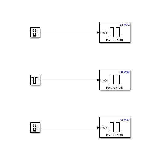
1. Configure the target model to make the LED light blink at a sample rate that you specified in the model.
2. Double-click the GPIO blocks to open the block parameter dialog box and ensure the following pin numbers are configured.
Green LED is connected to pin 0 of the GPIOB port.
Blue LED is connected to pin 7 of the GPIOB port.
Red LED is connected to pin 14 of the GPIOB port.
3. Configure the same pins (PB0,PB7,PB14) as GPIO_Output in your STM32CubeMX project to toggle user LED. For more information, see FreeRTOS STM32CubeMX Project Configurations.
Configure the Simulink Model
1. Open the FREERTOS_gettingstarted model.
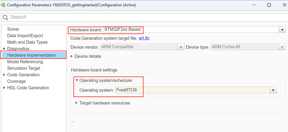
2. Press Ctrl+E to open the Configuration Parameters dialog box. Click Hardware Implementation in the left pane. Set Hardware board to STM32F2xx Based.
3. Under Hardware board settings, expand Operating system/scheduler and set Operating system to FreeRTOS.
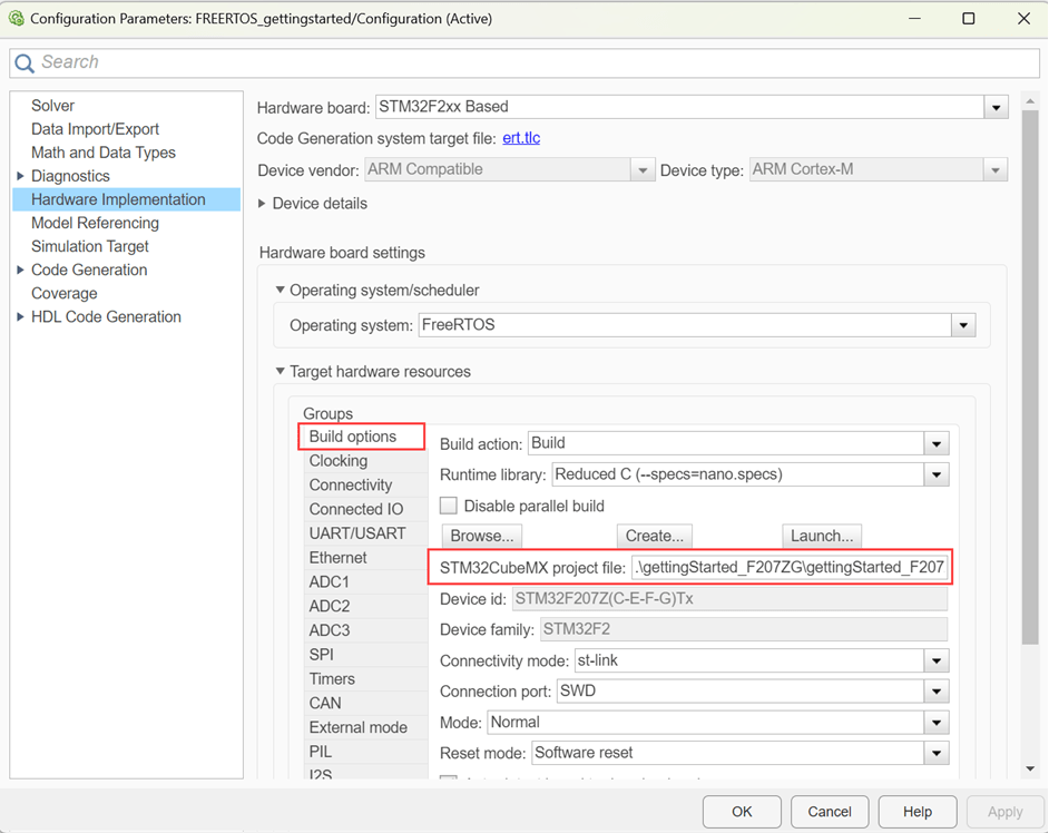
4. Go to Build options and click Browse to select gettingStarted_F2027ZG.ioc STM32CubeMX project file. For more information on STM32CubeMX Project, see Getting Started with STMicroelectronics STM32 Processor Based Boards.
5. Consider the following Simulink configurations when you set Operating system to FreeRTOS:
When using FreeRTOS, ensure to set your model base rate to a value greater than or equal to
1ms.The
FreeRTOSsupports a maximum of56thread priorities i.e. between (0 - 55), in which1 - 40thread priorities can be used for scheduling model rates.41-55thread priorities are reserved for custom used defined higher priority threads. Idle thread priority is reserved for external mode simulation.
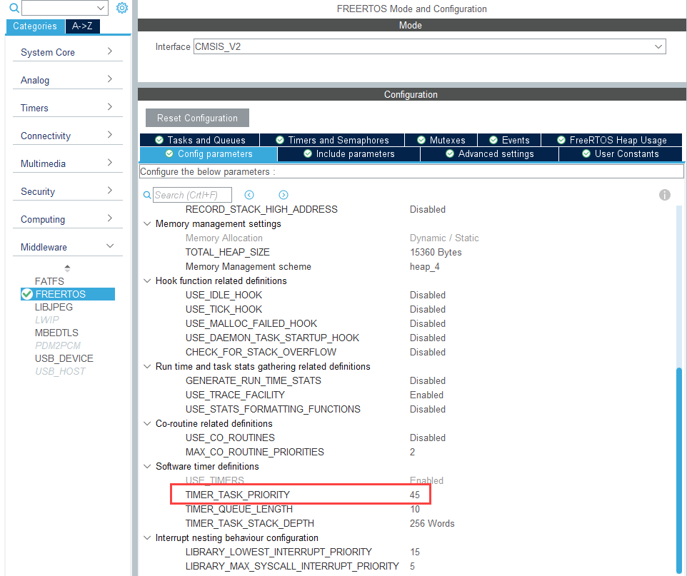
Note: Software timer is used for scheduling the model rates. The timer task priority should be set to a priority greater than the highest scheduling rate (40 is the base rate).
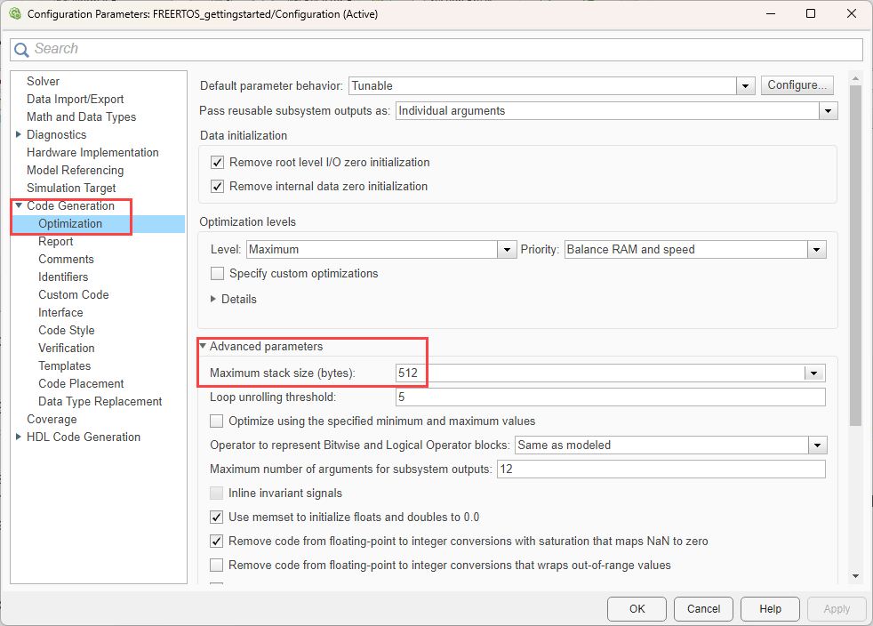
When using the FreeRTOS, the value that you specify in Configuration Parameters > Code Generation > Optimization > Advance parameters > Maximum stack size list applies to each thread. However, the specified stack size may not be fully utilized in some of the threads.
Note: The stack size of a thread is set as maximum in Configuration Parameters > Code Generation > Optimization > Advance parameters > Maximum stack size and STM32CubeMX > Middleware > FREERTOS > Kernel settings > Config parameters > Minimal stack size.
FreeRTOS STM32CubeMX Project Configurations
When you select FreeRTOS as operating system, ensure the following settings are configured in STM32CubeMX project.
1. Open the gettingStarted_F2027ZG.ioc file.
2. Configure the pin (PB0) as GPIO_Output in your STM32CubeMX project to toggle user LED.
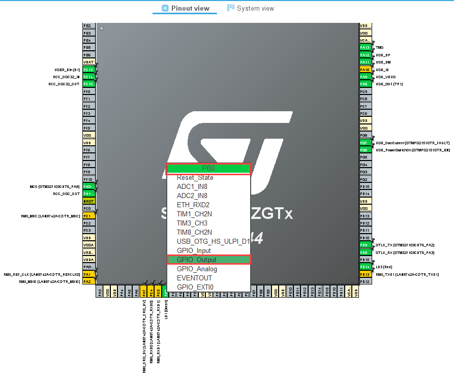
3. Similarly configure the other pins PB7 and PB14 as GPIO_Output in the IOC file.

4. Select the Interface as CMSIS_V2 in STM32CubeMX > Middleware > FREERTOS > Interface.
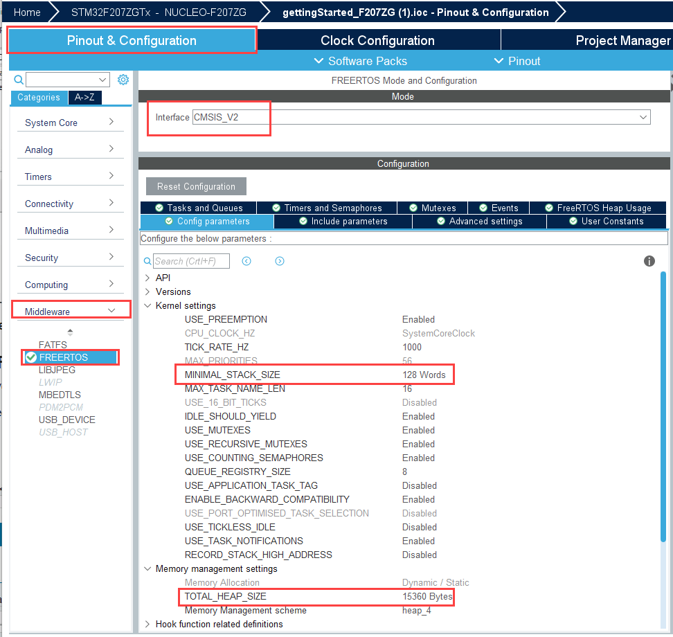
5. Ensure to allocate enough heap size and timer task priority greater than 40.
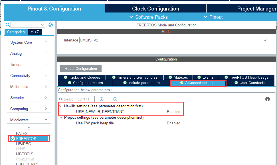
6. Set USE_NEWLIB_REENTRANT to Enabled in STM32CubeMX > Middleware > FREERTOS > Advanced settings > Newlib settings.
Generate Code and Load on Hardware Board from Simulink Model
1. To generate the code for the model, press Ctrl+B or click Build, Deploy & Start.

2. Follow the build process by opening the diagnostic viewer using the link provided at the bottom of the model canvas. After you load the code on the board, a LED blinks on the hardware board, indicating that the code is running.