Hauptinhalt

QSPI Controller

R2026b

Write data to and read data from an SPI peripheral device

Since R2024a

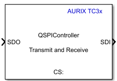
  • QSPI controllerl block icon

Libraries:
Embedded Coder Support Package for Infineon AURIX TC3x Microcontrollers / AURIX TC3x

Description

Add-On Required: This feature requires the Embedded Coder Support Package for Infineon AURIX TC3x Microcontrollers add-on.

Write data to and read data from an SPI peripheral device.

The Queued Synchronous Peripheral Interface (QSPI) controller block accepts 1-D array of data type int8, uint8, int16, uint16, int32, and uint32.

In SPI Transmit and Receive transfer mode, the block output emits an array that matches the input data size and the data type you specify in the Output data type parameter. In SPI Receive transfer mode, the block output emits an array with data type and size you specify in the Output data length and Output data type parameters.

This block generates and configures the SDI, SDO, clock and chip select signals for the QSPI devices.

Examples
Ports

Input

expand all

This port accepts the data to be transmitted to the peripheral device, with the data type defined by the Data bits and Output data type parameters.

Dependencies

To enable this port, set the Transfer mode parameter to either SPI Transmit and Receive or SPI Transmit.

Data Types: int8 | uint8 | int16 | uint16 | int32 | uint32

If you set the Transfer mode parameter to either SPI Transmit and Receive or SPI Receive, the QSPI block converts the SoC message SDImsg into output data at the SDI output port during simulation.

Dependencies

To enable this port, select the Enable simulation port parameter and set the port type as SoC Data (Message based).

If you set the Transfer modeparameter to either SPI Transmit and Receive or SPI Receive, this input port acts as pass-through with the SDI output of QSPI block during simulation.

Dependencies

To enable this port, select the Enable simulation port parameter and set the port type as Signal.

Output

expand all

This port outputs the data received from the peripheral device.

In SPI Transmit and Receive transfer mode, the block output emits an array that matches the input data size and the data type you specify in the Output data type parameter. In SPI Receive transfer mode, the block output emits an array with data type and size you specify in the Output data length and Output data type parameters.

Dependencies

To enable this port, set the Transfer mode parameter to either SPI Transmit and Receive or SPI Receive.

Data Types: int8 | uint8 | int16 | uint16 | int32 | uint32

The block emits the status of the data that was received, or the errors that occurred during the data transmission and reception, as a unit16 scalar value

Bit Status
Bit 0Transaction successful
Bit 1Busy
Bit 2Parity error
Bit 3Configuration error
Bit 4Baud rate error
Bit 5Transmit buffer (Tx FIFO) overflow error
Bit 6Tx FIFO underflow error
Bit 7Receive buffer (Rx FIFO) overflow error
Bit 8Rx FIFO underflow error
Bit 9Timeout error

For example, the status of 17 (sets 4th and 0th bit) represents successful transaction with baud rate error.

Dependencies

To enable this port, select the Enable status port parameter.

Data Types: uint16

If you set the Transfer modeparameter to either SPI Transmit and Receive or SPI Transmit, this port outputs the data received at SDO port in message form during simulation.

Dependencies

To enable this port, select the Enable simulation port parameter and set the port type as SoC Data (Message based).

If the Transfer mode is set to either SPI Transmit and Receive or SPI Transmit, this port outputs the data received at SDO port during simulation.

Dependencies

To enable this port, select the Enable simulation port parameter and set the port type as Signal.

Parameters

expand all

Basic

Select one of these operation modes:

  • SPI Transmit and Receive — In this mode, the block transmits data to the peripheral device while simultaneously receiving data from it. The block waits until the complete data is received before it continues processing.

    When you select this transfer mode, the block enables both the SDO and SDI ports.

  • SPI Transmit — In this mode, the block transmits data to the peripheral device. When you select this transfer mode, the block configures an input port, SDO.

  • SPI Receive — In this transfer mode, the block receives data from peripheral device. When you select this transfer mode, the block enables an output port, SDI.

This parameter specifies the frame length of each data element used in QSPI communication. The selected frame length determines the valid data type for the SDO and SDI ports.

  • For frame length 2 to 8, the valid data types are int8 or unit8.

  • For frame length 9 to 16, the valid data types are int16 or unit16.

  • For frame length 17 to 32, the valid data types are int32 or unit32.

Select this parameter to output status of data transfer.

When you select this parameter, the block enables the status port.

Specify in seconds how often the block should read the input data.

When you specify this parameter as -1, Simulink® determines the best sample time for the block based on the block context within the model.

Dependencies

To enable this parameter, set the Transfer mode to the SPI Receive.

Select this parameter to enable peripheral simulation capability.

Select this parameter to configure either the SoC compatible or the Simulink signal based simulation ports to enable peripheral simulation capability.

Dependencies

To enable this parameter, select the Enable simulation port parameter.

Advanced

Specify the data length to be received from the peripheral device.

Note

The data length specified must match the data transmitted using QSPI Peripheral block.

Dependencies

To enable this parameter, set the Transfer mode to the SPI Receive

Select the supported data types based on the data bits selected.

Dependencies

To enable this parameter, set the Transfer mode to either SPI Receive or SPI Transmit and Receive.

Version History

Introduced in R2024a