Farrow Rate Converter
Polynomial sample-rate converter with arbitrary conversion factor
Libraries:
DSP System Toolbox /
Signal Operations
DSP System Toolbox /
Filtering /
Multirate Filters
Description
The Farrow Rate Converter block converts the sample rate of an input signal using polynomial-fit sample-rate conversion. Polynomial-based filters are efficient at implementing fractional sample rate conversion. Farrow structures are implementations of polynomial-based filters. This block uses a Farrow structure to implement arbitrary rate-change factors efficiently. The rate-change factors can be irrational.
Ports
Input
Output
Parameters
Main Tab
Specify the sample rate of the input signal as a positive scalar in Hz. The input sample rate must be greater than the bandwidth of interest.
Specify the sample rate of the output signal as a positive scalar in Hz. The output sample rate must be higher or lower than the input sample rate.
Specify the maximum tolerance for the output sample rate as a positive scalar in the
range [00.5].
The actual output sample rate varies but is within the specified range. For example, if you set the Tolerance for output sample rate to 0.01, then the actual output sample rate is in the range given by sample rate of output signal ± 1%. This flexibility allows for a simpler filter design.
Specify the method the block uses to determine the polynomial interpolator coefficients as one of the following:
Polynomial order— Specify the order of the Lagrange interpolation filter polynomial through the Polynomial order parameter.Coefficients— Specify the polynomial coefficients directly through the Coefficients parameter.
Specify the filter polynomial coefficients as a real-valued square matrix.
Dependencies
To enable this parameter, set Filter specification method to
Coefficients.
Specify the order of the Lagrange-interpolation-filter polynomial as
1, 2, 3, or
4.
Dependencies
To enable this parameter, set Filter specification method to
Polynomial order.
Specify whether fixed-size input signals (whose size does not change during simulation) can have an arbitrary frame length, where the frame length does not have to be a multiple of the decimation factor. The block uses this parameter setting only for fixed-size input signals and ignores this parameter if the input has a variable-size.
When the input signal is a variable-size signal, the signal can have arbitrary frame length, that is, the frame length does not have to be a multiple of the decimation factor.
For fixed-size input signals, if you:
Select the Allow arbitrary frame length for fixed-size input signals parameter, the frame length of the signal does not have to be a multiple of the decimation factor. If the input is not a multiple of the decimation factor, then the output is generally a variable-size signal. Therefore, to support arbitrary input size, the block must also support variable-size operations, which you can enable by selecting the Allow arbitrary frame length for fixed-size input signals parameter.
Clear the Allow arbitrary frame length for fixed-size input signals parameter, the input frame length must be a multiple of the decimation factor.
Opens the FVTool and displays the magnitude/phase response of the Farrow Rate Converter. The response is based on the block parameters. FVTool updates when you change the parameters.
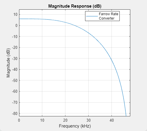
To update the magnitude response while FVTool is running, modify the parameters in the dialog box and click Apply.
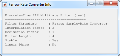
Click this button for the block to display the following information about the Farrow filter system:
Filter StructureInterpolation FactorDecimation FactorFilter LengthStableLinear Phase
This button brings the functionality of the info method into the
Simulink® environment.
Specify the type of simulation to run. You can set this parameter to:
Interpreted execution— Simulate model using the MATLAB® interpreter. This option shortens startup time.Code generation— Simulate model using generated C code. The first time you run a simulation, Simulink generates C code for the block. The C code is reused for subsequent simulations as long as the model does not change. This option requires additional startup time but provides faster subsequent simulations.
Data Types Tab
Specify the rounding mode for fixed-point operations as one of the following:
FloorCeilingConvergentNearestRoundSimplestZero
For more details, see rounding mode.
When you select this parameter, the block saturates the result of its
fixed-point operation. When you clear this parameter, the block wraps
the result of its fixed-point operation. For details on
saturate and wrap, see overflow
mode for fixed-point operations.
Specify the data type of the filter coefficients as a signed fixed-point object. The
default fixdt(1,16) corresponds to a signed
fixed-point type object with 16-bit coefficients. For maximum precision,
the block determines the fraction length based on the coefficient
values.
Specify the data type of the fractional delay as an unsigned fixed-point object. The
default fixdt(0,8) corresponds to an unsigned
fixed-point data type object with 8-bit word length. For maximum
precision, the block computes the fractional length based on the
fractional delay values.
Specify the multiplicand data type as a signed fixed-point object. The
default fixdt(1,16,13) corresponds to a
signed fixed-point multiplicand data type with 16-bit word length and
13-bit fraction length.
Specify the word length and fraction length of the output data type as one of the following:
Inherit: Same word length as
											input
(default) — Output word length and fraction lengths are the same as the input.Inherit: Same as accumulator— Output word length and fraction lengths are the same as the accumulator.fixdt(1,16)— Signed fixed-point data type with 16-bit word length. For maximum precision, the block computes the fraction length based on the input range and preserves the dynamic range of the input.fixdt(1,16,0)— Signed fixed-point data type with 16-bit word length and zero fraction length.
Specify the minimum value that the block can output. Simulink software uses this minimum value to perform:
Simulation range checking. See Specify Signal Ranges (Simulink).
Automatic scaling of fixed-point data types.
Specify the maximum value that the block can output. Simulink software uses this maximum value to perform:
Simulation range checking. See Specify Signal Ranges (Simulink).
Automatic scaling of fixed-point data types.
Block Characteristics
Data Types |
|
Direct Feedthrough |
|
Multidimensional Signals |
|
Variable-Size Signals |
|
Zero-Crossing Detection |
|
More About
The diagram shows the data types that the Farrow Rate Converter
block uses for fixed-point signals and floating-point signals. You can specify these
data types using the parameters on the Data Types tab. If the
input is floating point, all data types in the filter are the same as the input data
type, single or double.
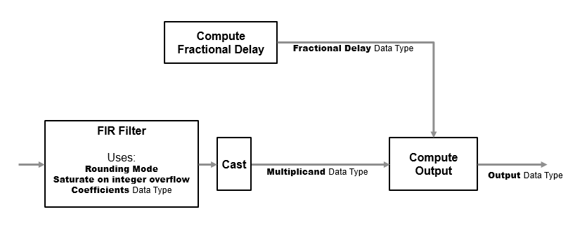
If the input is fixed point, the FIR filter defines internal data types using the Rounding mode, Saturate on integer overflow, and Coefficients parameters. The accumulators and products within the FIR filter use full-precision data types. The block casts the output of the FIR filter to the Multiplicand data type.
Algorithms
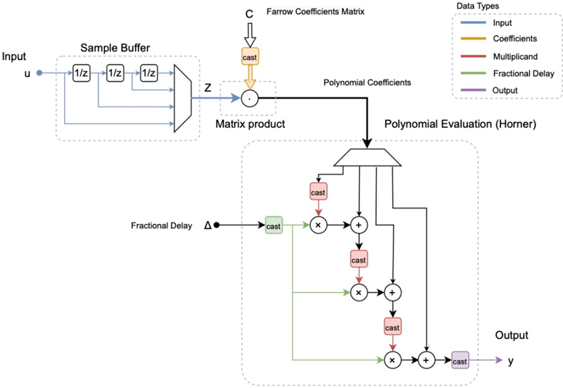
Farrow filters implement piecewise polynomial interpolation using Horner’s rule to compute samples from the polynomial. The polynomial coefficients used to fit the input samples correspond to the Lagrange interpolation coefficients.
Once a polynomial is fitted to the input data, the value of the polynomial can be calculated at any point. Therefore, a polynomial filter enables interpolation at arbitrary locations between input samples.
You can use a polynomial of any order to fit to the existing samples. However, since large-order polynomials frequently oscillate, polynomials of order 1, 2, 3, or 4 are used in practice.
The algorithm computes interpolated values at the desired locations by varying only the fractional delay µ. This value is the interval between the previous input sample and the current output sample. All filter coefficients remain constant.
The input samples are filtered using M + 1 FIR filters, where M is the polynomial order.
The outputs of these filters are multiplied by the fractional delay, µ.
The output is the sum of the multiplication results.
Here is the filter structure diagram of the Farrow filter with a polynomial order of 4.