Forward Vehicle Sensor Fusion
This example shows how to simulate sensor fusion and tracking in a 3D simulation environment for automated driving applications. The example also shows how to use performance metrics to evaluate the performance of a tracker in an open-loop environment.
Introduction
Autonomous vehicle uses multiple sensors, including cameras and radar, to perceive the surrounding environment. However, each sensor has its own limitations. Fusing information from various sensors can make vehicle perception more robust. Sensor fusion and tracking is central to the decision-making process in various systems, including highway lane following and forward collision warning. By using the sensor fusion and tracking model in this example, you can run tests on critical scenarios that are in reality difficult to implement. In this example, you perform the following steps.
Explore the test bench model — The model contains sensors, sensor fusion and tracking algorithm, and metrics to assess functionality. An equivalent Unreal Engine® scene is used to model detections from a radar sensor and a vision sensor.
Configure sensors and the environment — Set up a driving scenario that includes an ego vehicle with camera and radar sensor. Plot the coverage area of each sensor using bird's-eye scope.
Perform sensor fusion and tracking — Combine information from the two sensors using a joint probabilistic data association (JPDA) multi-object tracker to track the objects around the ego vehicle.
Evaluate the tracker performance — Use the generalized optimal subpattern assignment (GOSPA) metric to evaluate the performance of the tracker.
Simulate the test bench model and analyze the results — You can configure the test bench model for different scenarios. By default, the model configures a scenario where target vehicles come close to each other in front of the ego vehicle in three adjacent lanes and pose a challenge for the tracking system. Simulate the model and analyze the components of the GOSPA metric to understand the tracker performance.
This example tests the sensor fusion and tracking algorithm in a 3D simulation environment that uses the Unreal Engine® from Epic Games®.
if ~ispc
    error(['This example is only supported on Microsoft', char(174), ' Windows', char(174), '.']);
end
Explore Test Bench Model
To explore the test bench model, load the forward vehicle sensor fusion project.
openProject("FVSensorFusion");
Open the test bench model.
open_system('ForwardVehicleSensorFusionTestBench');
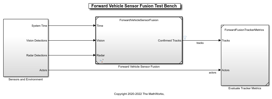
Opening this model runs the helperSLForwardVehicleSensorFusionSetup script, which initializes the scenario using the drivingScenario object in the base workspace. It also configures the sensor fusion and tracking parameters, vehicle parameters, and the Simulink® bus signals required for defining the inputs and outputs for the ForwardVehicleSensorFusionTestBench model. The test bench model contains these subsystems:
Sensors and Environment — This subsystem specifies the scene, vehicles, and sensors used for simulation.
Forward Vehicle Sensor Fusion — This subsystem implements the radar clustering, detection concatenation, fusion, and tracking algorithms.
Evaluate Tracker Metrics — This subsystem assesses the tracker performance using GOSPA metric between a set of tracks and their ground truths.
Configure Sensors and Environment
The Sensors and Environment subsystem configures the road network, places vehicles, and synthesizes sensors. For an example that uses a similar subsystem, see Highway Lane Following. Open the Sensors and Environment subsystem.
open_system('ForwardVehicleSensorFusionTestBench/Sensors and Environment');

The subsystem includes two sensor blocks: Simulation 3D Probabilistic Radar and Simulation 3D Vision Detection Generator. The parameters of these models are set by the helperSLForwardVehicleSensorFusionSetup script when you open the test bench model. These blocks generate detections from the 3D simulation environment.
The Simulation 3D Probabilistic Radar block generates object detections based on a statistical model. This sensor is mounted on the ego vehicle at an offset specified by the
PositionandRotationparameters of theradarstructure.
disp(radar');
        FieldOfView: [40 5]
    DetectionRanges: [1 100]
           Position: [3.7290 0 0.8000]
      PositionSim3d: [2.4240 0 0.8000]
           Rotation: [0 0 0]
The Simulation 3D Vision Detection Generator block generates detections from camera measurements taken by a vision sensor mounted on the ego vehicle at an offset specified by the
PositionandRotationparameters of thecamerastructure.
disp(camera');
             NumColumns: 1024
                NumRows: 768
            FieldOfView: [45 45]
              ImageSize: [768 1024]
         PrincipalPoint: [512 384]
            FocalLength: [512 512]
               Position: [1.8750 0 1.2000]
          PositionSim3d: [0.5700 0 1.2000]
               Rotation: [0 0 0]
        DetectionRanges: [6 50]
    LaneDetectionRanges: [6 30]
       MeasurementNoise: [3×3 double]
     MinObjectImageSize: [10 10]
The bird's-eye scope displays sensor coverages by using a cuboid representation. The radar coverage area and detections are in red. The vision coverage area and detections are in blue.
Perform Sensor Fusion and Tracking
The Forward Vehicle Sensor Fusion model is the reference model that processes vision and radar detections and generates the position and velocity of the tracks relative to the ego vehicle. Open the Forward Vehicle Sensor Fusion reference model.
open_system('ForwardVehicleSensorFusion');

The Forward Vehicle Sensor Fusion reference model contains these blocks:
Detection Clustering — Cluster multiple radar detections, since the tracker expects at most one detection per object per sensor.
Detection Concatenation — Combine the vision and radar detections onto a single output bus.
JPDA Tracker — Perform fusion and manage the tracks of stationary and moving objects.
The JPDA Tracker block is a key block of the Forward Vehicle Sensor Fusion reference model. The tracker fuses the information contained in concatenated detections and tracks the objects around the ego vehicle. The tracker outputs a list of confirmed tracks. These tracks are updated at prediction time, driven by a digital clock in the Sensors and Environment subsystem.
Evaluate Performance of Tracker
The Evaluate Tracker Metrics subsystem computes various metrics to assess the performance of a tracker. Open the Evaluate Tracker Metrics subsystem.
open_system('ForwardVehicleSensorFusionTestBench/Evaluate Tracker Metrics');

To evaluate tracker performance, you must to remove the actors that are outside the coverage area of the sensors from the ground truth information. For this purpose, the subsystem uses the Filter Within Coverage block to filter only those actors that are within the coverage area of the sensors.
The subsystem contains GOSPA metric block, which computes these metrics:
GOSPA metric — This metric measures the distance between a set of tracks and their ground truths, and combines both assignment and state-estimation accuracy into a single cost value.
Localization error — This error indicates the state-estimation accuracy. A higher value indicates that the assigned tracks do not estimate the state of the truths correctly.
Missed target error — This error indicates the presence of missed targets. A higher value indicates that targets are not being tracked.
False track error — This error indicates the presence of false tracks.
Simulate Test Bench Model and Analyze Results
During simulation, you can visualize the scenario in both the 3D simulation window and using bird's-eye scope.
To open the scope, click Bird's-Eye Scope in the Review Results section of the Simulink toolstrip. Next, click Update Signals to find and update signals that the scope can display.
Configure the ForwardVehicleSensorFusionTestBench model to simulate the scenario_LFACC_03_Curve_StopnGo scenario. This scenario contains six vehicles, including the ego vehicle. The scenario function also defines their trajectories. In this scenario, the ego vehicle has a lead vehicle in its lane. In the lane to the right of the ego vehicle, target vehicles indicated in green and blue are traveling in the same direction. In the lane to the left of the ego vehicle, target vehicles indicated in yellow and purple are traveling in the opposite direction.
helperSLForwardVehicleSensorFusionSetup("scenarioFcnName","scenario_LFACC_03_Curve_StopnGo");
Simulate the test bench model.
sim('ForwardVehicleSensorFusionTestBench');
Simulation opens the 3D Simulation window, which displays the scenario but does not display detections or sensor coverage. Use the Bird's-Eye Scope window to visualize the ego actor, target actors, sensor coverage and detections, and confirmed tracks. To visualize only the sensor data, turn off the 3D Simulation window during simulation by clearing the Display 3D simulation window parameter in the Simulation 3D Scene Configuration block.

During the simulation, the model outputs the GOSPA metric and its components. The model logs the metrics, with the confirmed tracks and ground truth information, to the base workspace variable logsout. You can plot the values in logsout by using the helperPlotForwardVehicleSensorFusionResults function.
helperPlotForwardVehicleSensorFusionResults(logsout);

The plots show that the localization error accounts for most of the GOSPA metric values. Notice that the missed target component starts from a high value, due to establishment delay of the tracker, and goes down to zero after some time. The other peaks in the missed target curve occur because there were no detections for the opposite vehicles initially as they are occluded due to lead vehicle and also once the vehicles approaches the ego vehicle in the opposite direction, there is some establishment delay of the tracker causing peaks in missed target.
Explore Other Scenarios
You can use the procedure in this example to explore these other scenarios, which are compatible with ForwardVehicleSensorFusionTestBench :
scenario_LFACC_01_Curve_DecelTarget
scenario_LFACC_02_Curve_AutoRetarget
scenario_LFACC_03_Curve_StopnGo [Default]
scenario_LFACC_04_Curve_CutInOut
scenario_LFACC_05_Curve_CutInOut_TooClose
scenario_LFACC_06_Straight_StopandGoLeadCar
scenario_FVSF_01_Curve_FourVehicles
scenario_FVSF_02_Straight_FourVehicles
scenario_FVSF_03_Curve_SixVehicles
Use these additional scenarios to analyze ForwardVehicleSensorFusionTestBench under different conditions.
Conclusion
This example showed how to simulate and evaluate the performance of the sensor fusion and tracking component for automated driving application. This component-level model lets you stress test your design in open-loop virtual environment and helps in tuning the tracker parameters by evaluating GOSPA metrics. The next logical step is to integrate this component-level model in closed-loop system like highway lane following.
See Also
Scenario Reader | Vehicle To World | Simulation 3D Scene Configuration | Cuboid To 3D Simulation | Multi-Object Tracker
Topics
- Integrate and Verify C++ Code of Sensor Fusion Algorithm in Simulink
- Automate Testing for Forward Vehicle Sensor Fusion
- Automate Real-Time Testing for Forward Vehicle Sensor Fusion
- Automate PIL Testing for Forward Vehicle Sensor Fusion
- Lane Following Control with Sensor Fusion and Lane Detection
- Highway Lane Following
- Design Lane Marker Detector Using Unreal Engine Simulation Environment
- Surround Vehicle Sensor Fusion