Descrambler
Descramble input signal
Libraries:
Communications Toolbox /
Sequence Operations
Description
The Descrambler block applies multiplicative descrambling to input data. It performs the inverse operation of the Scrambler block used in the transmitter.
This schematic shows the multiplicative descrambler operation. The adders and
subtracter operate modulo N, where N is the value
specified by the Calculation base
parameter.
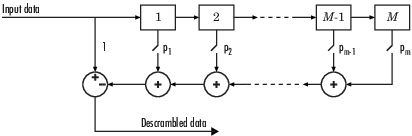
At each time step, the input causes the contents of the registers to shift
sequentially. Using the Scramble polynomial
parameter, you specify the on or off state for each switch in the descrambler. To make
the Descrambler block reverse the operation of the
Scrambler block, use the same parameter settings in both blocks. If
there is no signal delay between the scrambler and the descrambler, then the
Initial states in the two blocks must be the same.
To achieve repeatable initial descrambler conditions, you can use one of these optional input ports:
Select the
Reset on
                            nonzero input via port
parameter and reset the scrambler withRst.Set the
Initial states
                            source
parameter toInput portand provide the initial states withISt.
This block can accept input sequences that vary in length during simulation. For more information about sequences that vary in length, see Variable-Size Signal Basics (Simulink).
Note
To apply additive descrambling to input data, you can use the PN Sequence Generator block and the Logical Operator (Simulink) block configured as an XOR logical operator. For an example, see Additive Scrambling of Input Data in Simulink.
Examples
The slexScramblerDescrambler model illustrates use of a scrambler-descrambler block pair.

The Scrambler and Descrambler block pair are initialized to the same values by setting block parameters to variables assigned using the InitFcn Callback. To view or change the initialization values, go to File > Model Properties > Callbacks > InitFcn. When you run the model, it displays the percentage of zeros at the input to the scrambler, output from the scrambler and output from the descrambler. For a binary signal, the scrambler outputs zeros or ones with equal probability. For perfect data recovery, the bit error rate is zero.
Extended Examples

QPSK Transmitter and Receiver
Model a QPSK transmitter and receiver in Simulink®.
Ports
Input
Output
Parameters
Block Characteristics
Data Types |
|
Multidimensional Signals |
|
Variable-Size Signals |
|
Extended Capabilities
Version History
Introduced before R2006a