Design and Simulate AUTOSAR Components and Generate Code
Develop AUTOSAR components by implementing behavior algorithms, simulating components and compositions, and generating component code.
Begin with Simulink Representation of AUTOSAR Components
To develop AUTOSAR components in Simulink®, you first create a Simulink representation of an AUTOSAR software component. AUTOSAR component creation can start from an ARXML component description or an existing Simulink design.
To import an AUTOSAR software component description from ARXML files and create an initial Simulink model representation, see example Import AUTOSAR Component to Simulink or example Import AUTOSAR Composition to Simulink.
To create an initial model representation of an AUTOSAR software component in Simulink, see Create AUTOSAR Software Component in Simulink.
This example uses a Simulink representation of an AUTOSAR software composition named autosar_composition, which models a throttle position control system. The composition contains six interconnected AUTOSAR software components -- four sensor/actuator components and two application components.
Open the composition model autosar_composition.
open_system("autosar_composition");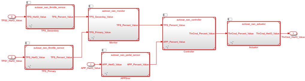
Signal lines between component models represent AUTOSAR assembly connectors. Signal lines between component models and data inports and outports represent AUTOSAR delegation connectors.
In a composition model, component models can be rate-based, function-call based, or a mix of both. This composition contains rate-based component models. In each component model, atomic subsystems model AUTOSAR periodic runnables. To allow rate-based runnable tasks to be scheduled on the same basis as exported functions, the component models use the Model block option Schedule rates. This option displays model periodic event ports for rate-based models.

Functional Overview of Throttle Position Control Composition
The objective of the composition model autosar_composition is to control an automotive throttle based on input from an accelerator pedal and feedback from the throttle. Inside the composition, a controller component takes input values from an accelerator pedal position (APP) sensor and two throttle position sensors (TPSs). The controller then translates the values into input values for a throttle actuator. The throttle actuator generates a hardware command that adjusts the throttle position.
The composition model has root inports for an accelerator pedal sensor and two throttle sensors, and a root outport for a command to throttle hardware. The composition requires sensor input values to arrive already normalized to analog/digital converter (ADC) range. The composition components are three sensors, one monitor, one controller, and one actuator.
Sensor component model
autosar_swc_pedal_sensortakes an APP sensor HWIO value from a composition inport and converts it to an APP sensor percent value.Primary and secondary instances of sensor component model
autosar_swc_throttle_sensortake TPS HWIO values from composition inports and convert them to TPS percent values.Application component model
autosar_swc_monitordecides which TPS signal to pass through to the controller.Application component model
autosar_swc_controllertakes the APP sensor percent value from the pedal sensor and the TPS percent value provided by the TPS monitor. Based on these values, the controller calculates a throttle command percent value to provide to the throttle actuator.Actuator component model
autosar_swc_actuatortakes the throttle command percent value provided by the controller and converts it to a throttle command HWIO value.
Develop AUTOSAR Component Algorithms
After creating initial Simulink representations of one or more AUTOSAR software components, you develop the components by refining the AUTOSAR configuration and creating algorithmic model content.
To develop AUTOSAR component algorithms, open each component and provide Simulink content that implements the component behavior. For example, consider the autosar_swc_controller component model in the autosar_composition model. When first imported or created in Simulink, the initial representation of the autosar_swc_controller component likely contained an initial stub implementation of the controller behavior.

Component model autosar_swc_controller provides this implementation of the throttle position controller behavior. The component takes as inputs an APP sensor percent value from a pedal position sensor and a TPS percent value provided by a throttle position sensor monitor. Based on these values, the controller calculates the error, which is the difference between where the automobile driver wants the throttle, based on the pedal sensor, and the current throttle position. A Discrete PID Controller block uses the error value to calculate a throttle command percent value to provide to a throttle actuator. A scope displays the error value and the Discrete PID Controller block output value over time.

The sensor and actuator component models in the autosar_composition model use lookup tables to implement their value conversions. For example, consider the autosar_swc_actuator component model. When first imported or created in Simulink, the initial representation of the autosar_swc_actuator component likely contained an initial stub implementation of the actuator behavior.
![]()
Component model autosar_swc_actuator provides this implementation of the throttle position actuator behavior. The component takes the throttle command percent value provided by the controller and converts it to a throttle command HWIO value. A hardware bridge command lookup table generates the output value.

The monitor component model in the autosar_composition model implements logic for selecting which TPS signal to provide to the controller component. When first imported or created in Simulink, the initial representation of the autosar_swc_monitor component likely contained an initial stub implementation of the monitor behavior.

Component model autosar_swc_monitor provides this implementation of the throttle position monitor behavior. The component takes TPS percent values from primary and secondary throttle position sensors and decides which TPS signal to pass through to the controller. A Switch block determines which value is passed through, based on sensor selection logic.

Simulate AUTOSAR Components and Composition
As you develop AUTOSAR components, you can simulate component models individually or as a group in a containing composition.
Simulate the implemented Controller component model.
open_system("autosar_swc_controller");
simOutComponent = sim("autosar_swc_controller");
close_system("autosar_swc_controller");
Simulate the autosar_composition model.
simOutComposition = sim("autosar_composition");Generate AUTOSAR Component Code (Embedded Coder)
As you develop each AUTOSAR component, if you have Simulink Coder and Embedded Coder software, you can generate ARXML component description files and algorithmic C code for testing in Simulink or integration into an AUTOSAR run-time environment.
For example, to build the implemented autosar_swc_controller component model, open the model. Press Ctrl+B or enter the MATLAB command slbuild("autosar_swc_controller").
The model build exports ARXML descriptions, generates AUTOSAR-compliant C code, and opens an HTML code generation report describing the generated files. In the report, you can examine the generated files and click hyperlinks to navigate between generated code and source blocks in the component model.
Alternatives for AUTOSAR System-Level Simulation
After you develop AUTOSAR components and compositions, you can test groups of components that belong together in a system-level simulation. You can:
Combine components in a composition for simulation.
Create a test harness with components, a scheduler, a plant model, and potentially Basic Software service components and callers. Use the test harness to perform an open-loop or closed-loop system simulation.
For an example of open-loop simulation that uses Simulink Test, see Testing AUTOSAR Compositions (Simulink Test). The example performs back-to-back testing for an AUTOSAR composition model.
For an example of a closed-loop simulation, open example model autosar_system. This model provides a system-level test harness for the AUTOSAR composition model autosar_composition.
open_system("autosar_system");

The objective of the system-level model autosar_system is performing system-level simulation of the plant and controller portions of the automotive throttle position control system. The system-level model combines the composition model autosar_composition with block representations of the physical accelerator pedal and throttle devices in a closed-loop system. The model takes output values from the pedal and throttle device blocks, converts the values to analog/digital converter (ADC) range, and provides the values as inputs to the composition. The system model also takes the throttle command HWIO value generated by the composition and converts it to an acceptable input value for the throttle device block. A system-level throttle position scope displays the accelerator pedal sensor input value against the throttle position sensor input value over time.
If you simulate the system-level model, the throttle position scope indicates how well the throttle-position control algorithms in the throttle composition model are tracking the accelerator pedal input. You can modify the system to improve the composition behavior. For example, you can modify component algorithms to bring the accelerator pedal and throttle position values closer in alignment or you can change a sensor source.
simOutSystem = sim("autosar_system");