Design H-Notch Patch Unit Element
This step of the tutorial shows how to design an unit element for a 1-by-2 H-notch linear array. You design the H-notch unit element by subtracting the top and bottom notches from the substrate.
Create H-Notch
Select the HNotchLayer on the PCB Stack navigation tree and then select Rectangle from the Shapes section on the toolbar. Drag the shape onto the canvas to create a rectangular patch.
Set the properties of Rectangle2 to the following:
Name —
HPatchCenter —
[0,0]Length —
20Width —
20

Click the Canvas Settings button and select Snap to grid to allow easier and more accurate drawing. Then set the Grid Size to 0.5 mm.

The app displays the drawn shape.

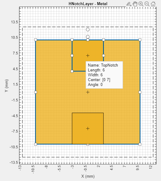
Create Top Notch
Select Rectangle from the Shapes section and drag the shape to the top of the shape to create a top notch in the patch layer. Set the properties of Rectangle3 to the following:
Name —
TopNotchCenter —
[0,7]Length —
6Width —
6

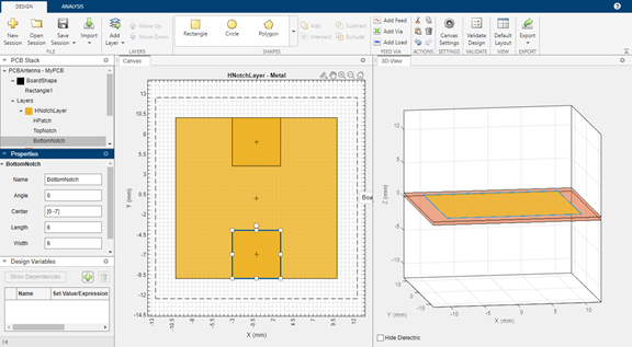
Create Bottom Notch
Select TopNotch from the canvas and then copy the layer by clicking Copy in the Actions section. Click Paste to paste a copy of TopNotch. Doing so creates a rectangle TopNotch_Copy_1 with identical dimensions to the TopNotch layer.
Set the properties of TopNotch_Copy_1 to the following:
Name —
BottomNotchCenter —
[0,-7]
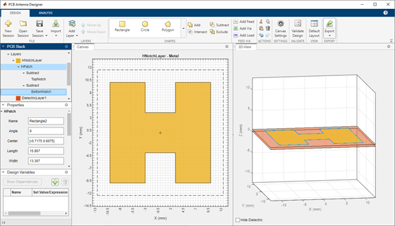
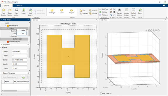
Subtract Top and Bottom Notch Layers from Metal Patch
Select HPatch and TopNotch and then click Subtract in the Shapes section of the toolbar to remove both rectangles.
The app updates the HPatch layer.

Select the HPatch and BottomNotch and click Subtract in the Shapes section of the toolbar to remove both rectangles.
Set Dimensions for Ground Plane
The ground plane must be same size as the HNotchLayer. To make the ground plane the same size as HPatch, right-click HPatch and select Copy.
Right-click the GroundPlane and click Paste on the toolbar to paste the rectangle in the GroundPlane.
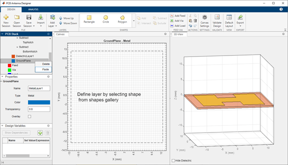
The app copies the rectangle to the ground plane layer with the name HPatch_Copy(1). HPatch_Copy(1) and HPatch have the same dimensions.
Set the properties of HPatch_Copy(1) to the following:
Name —
GroundPlaneRectCenter —
[0,0]Length —
23Width —
23

Add Feed
Select the HNotchLayer metal layer on the PCB Stack navigation tree and then click Add Feed in the Feed Via section on the toolbar. You can add a feed only to a metal layer.

As the PCB Stack navigation tree shows, the app adds the feed to HNotchLayer as Feed1.

For more information on feeds and vias, refer to the FeedLocation and ViaLocation properties in the documentation of the pcbStack object.
Change Properties of Feed
Select the parent Feed node on the PCB Stack navigation tree, and then set the FeedDiameter to 1 and FeedViaModel to Strip. FeedDiameter is a global property.

Change Position of Feed
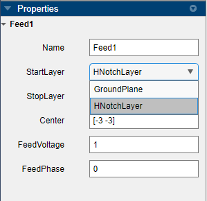
Select Feed1 on the PCB Stack navigation tree. In the Properties pane, set Center to [-3,-3].

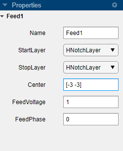
In the 3D-View pane, you can see that the feed is connected only to HNotchLayer.
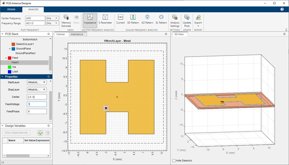
Change Start Layer and Stop Layer
Connect the feed from HNotchLayer to GroundPlane by setting StartLayer to HNotchLayer and StopLayer to GroundPlane. This creates a feed on the GroundPlane which connects to the HNotchLayer.


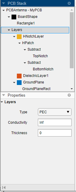
Change Metal Properties
Select the Layers in on the PCB Stack navigation tree and set the Type of the metal layer to Copper in the Properties pane.

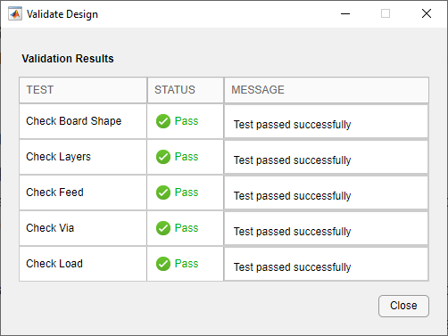
Validate Design
Click Validate Design on the toolbar to validate your board shape, layers, feed, via, and load.