Model Reconfigurable Intelligent Surfaces with CDL Channels
This example simulates a reconfigurable intelligent surface (RIS) channel using two concatenated clustered delay line (CDL) channel models and provides an iterative algorithm to control the phases of each RIS element. It then sends a 6G-like signal through the RIS channel and displays the constellation of the received signal.
System Model
This example models the scenario shown in the figure. An -antenna transmitter sends a complex symbol using a precoding vector of size . The example assumes there is no line of sight between the transmitter and the receiver. An -element RIS reflects the transmitted signal towards a single antenna receiver. and are the numbers of elements per row and column, respectively, in the RIS. The signal is affected by the channel matrix of size , which models the channel between the transmitter and the RIS. The th element of the RIS causes an amplitude and phase change to the impinging signal, which is modeled by the complex number . The reflected signal then travels towards the receiver through a channel modeled by matrix of size . The received signal is affected by noise .
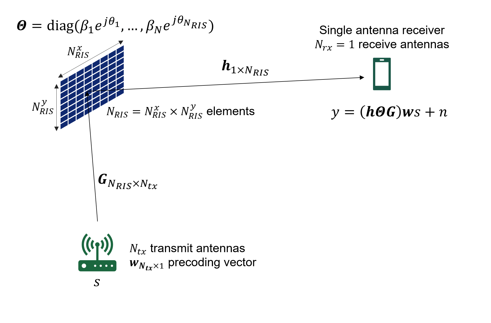
The example models both the channel between the transmitter and the RIS and the channel between the RIS and the receiver using CDL channels. To model the RIS, the example applies a phase rotation to each RIS element between both CDL channels. An iterative algorithm calculates the value of the phase shifts assuming knowledge of channel matrices and . This example also models path loss and the RIS scattering loss.
Where appropriate, the example uses parameters as defined in the group report from ETSI on RIS [1].
This example models the RIS with a stochastic channel model. For an introduction to RIS using a deterministic channel model, see the Introduction to Reconfigurable Intelligent Surfaces (RIS) (Phased Array System Toolbox) example.
Set Carrier and PDSCH Parameters
Set the carrier frequency, carrier configuration object, and PDSCH parameters. Calculate the sampling rate of the signal of interest.
rng('default')

fc = 28e9; % Carrier frequency (Hz)
carrier = pre6GCarrierConfig("NSizeGrid",50,"SubcarrierSpacing",120);
pdsch = pre6GPDSCHConfig("Modulation","16QAM","NumLayers",1,"PRBSet",0:carrier.NSizeGrid-1);

ofdmInfo = hpre6GOFDMInfo(carrier);
fs = ofdmInfo.SampleRate;
Set RIS and Transmit Array Parameters
The example assumes a multi-antenna transmitter, RIS elements, and a single-antenna receiver. The single-antenna receiver assumption simplifies the RIS control algorithm.
Specify the size of the transmit array. Use the format , where and are the number of rows and columns in the antenna array, respectively. is the number of polarizations (1 or 2). and are the number of row and column array panels, respectively.
% Transmit array
txArraySize = [4 2 2 1 1]; % [M N P Mg Ng]
Ntx =  prod(txArraySize(1:3));
Set ris.Enable to true to enable the RIS element phase optimization algorithm. Disabling this flag assigns random phase shifts to each RIS element, therefore disabling the desired operation of the RIS. Specify the number of elements in the RIS, their dimensions and , and the element gain . The size of the RIS is, where is the number of polarizations per RIS element (1 or 2).
% RIS parameters
ris.Enable = true;
ris.Size = [8 4 2];
numRISElements = prod(ris.Size);

% Wavelength
c = physconst("lightspeed");
lambda = c/fc;

% RIS element size
ris.dx = lambda/5;
ris.dy = lambda/5;

ris.A = 0.8; % Amplitude of reflection coefficients of each RIS element
Define RIS-Assisted Channel
This example models the propagation channel with two concatenated CDL channels. A phase rotation per RIS element between the CDL channels models the RIS. The hpre6GRISChannel object implements both CDL channels and the phase rotation per phase element. The hpre6GRISChannel class does not model the path loss, which is applied externally.
risCh = hpre6GRISChannel("SampleRate",ofdmInfo.SampleRate,"RISSize",ris.Size,"CarrierFrequency",fc);
risCh.TransmitAntennaArray.Size = txArraySize;
risCh.ReceiveAntennaArray.Size = [1 1 1 1 1]; % Receive array must be a single antenna in this example
risCh.Seed = randi([0,(2^32)-1]);             % Random seed

% Calculate the overall channel delay
chInfo = risCh.info;
channelDelay = chInfo.TxRISChInfo.MaximumChannelDelay + chInfo.RISRXChInfo.MaximumChannelDelay;
Specify the transmit power, noise, and interference-related parameters, as defined in the group report from ETSI on RIS [1].
txPower = 20;                                % dBm. Average transmit power per antenna
% Noise and interference parameters
noiseFigure = 7;                             % dB
thermalNoiseDensity = -174;                  % dBm/Hz
rxInterfDensity = -165.7;                    % dBm/Hz

% Calculate the corresponding noise power
totalNoiseDensity = 10*log10(10^((noiseFigure+thermalNoiseDensity)/10)+10^(rxInterfDensity/10));
BW = 12*carrier.NSizeGrid*carrier.SubcarrierSpacing*1e3;
noisePower = totalNoiseDensity+10*log10(BW); % dBm
N = 10^((noisePower-30)/10);                 % Linear
Calculate RIS Link Path Loss
The path loss for a RIS scenario in the far field case is given in the ETSI report as:
and are the transmit and receive antenna gains. is the scattering gain of a single RIS element. and represent the width and length of each RIS element. is the wavelength. and represent the normalized radiation pattern of each element in the direction of the transmitter and the receiver, respectively. and are the elevation and azimuth angles from the center of the RIS to the transmitter. represents the amplitude of reflection coefficients of each RIS element. It is assumed to be the same for all elements.
A common assumption of RIS element scattering gain is:
This example assumes . Therefore:
% Distance between Tx and RIS and RIS and Rx
dt = 105; % meters
dr = 7;   % meters

% Path loss (power gain)
PL = ((4*pi*dt*dr)/(prod(ris.Size(1:3))*ris.dx*ris.dy*ris.A)).^2;

disp("RIS link path loss "+10*log10(PL)+" dB")
RIS link path loss 151.8968 dB
Calculate Precoding Vector and RIS Elements Phase Value
This example uses a sub-optimal iterative approach to calculate the precoding vector and phase values . This approach is an iterative algorithm similar to the one described by Tao Zhou and Kui Xu [2]. For an initial set of phases , the algorithm calculates the set of precoding weights using maximum ratio transmission (MRT). Given the value of the precoding weights, the algorithm recalculates the set of phases such that the combined phase changes of both channels and , and the RIS, are constant. This process repeats iteratively until the values converge to a solution. This algorithm guarantees at least a locally optimal solution.
[risElementCoeff,w,overallChannel] = calculateRISCoeff(ris.Enable,risCh,carrier);
To calculate the values of and , this example calculates an average of the channel conditions over all subcarriers and OFDM symbols.
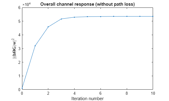
To check the convergence of the RIS phase calculation algorithm, plot the square of the magnitude of the overall channel response .
if ris.Enable
    plot(0:length(overallChannel)-1,abs(overallChannel).^2,'.-')
    xlabel("Iteration number");ylabel('$| (\mathbf{h} \mathbf{\Theta} \mathbf{G}) \mathbf{w}  |^2$', 'Interpreter', 'latex')
    title('Overall channel response (without path loss)')
end
Transmit and Receive Data
Generate one slot of a 6G-like frame and send it through the RIS-assisted channel. This example uses PDSCH uncoded bits (no channel coding). You can change the bandwidth and subcarrier spacing of this signal to explore the effect of RIS on 6G-like signals.
w = w.'; % transmitter requires w to be of the form number of layers by number of transmit antennas

[txWaveform,pdschSym,pdschInd,dmrsSym,dmrsInd,~,pdschGrid] = generateTxWaveform(carrier,pdsch,w,txPower);
Send the signal through the channel and add noise.
% Pad with zeros to flush full slot from the channel
txWaveform = [txWaveform; zeros(channelDelay,size(txWaveform,2))];

% Send signal through RIS assisted channel
rxWaveformNoisless = risCh(txWaveform,risElementCoeff);

% Apply path loss
rxWaveformNoisless = (1/sqrt(PL))* rxWaveformNoisless;

% Add noise
noise = sqrt(N)*randn(size(rxWaveformNoisless),"like",rxWaveformNoisless);
rxWaveform = rxWaveformNoisless+noise;

% Power measurements
Ptx = mean(rms(txWaveform).^2);
Prx = mean(rms(rxWaveformNoisless).^2);
disp("Avg tx power (per antenna) = "+(10*log10(Ptx)+30)+" dBm")
Avg tx power (per antenna) = 19.9955 dBm
disp("Avg rx power (per antenna) = "+(10*log10(Prx)+30)+" dBm")
Avg rx power (per antenna) = -72.5773 dBm
disp("SNR (time domain) = "+10*log10(mean(rms(rxWaveformNoisless).^2)/mean(rms(noise).^2))+" dB")
SNR (time domain) = 12.1343 dB
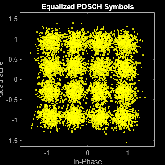
Decode the received signal and plot the equalized constellation.
% Perfect synchronization
[~,~,offsetTxRIS,offsetRISRx] = risCh.channelResponse(carrier);
rxWaveform = rxWaveform(1+offsetTxRIS+offsetRISRx:end,:);
% PDSCH decoding
[pdschEq,pdschRx] = decodePDSCH(rxWaveform,carrier,pdsch,pdschInd,dmrsSym,dmrsInd);

scatterplot(pdschEq); title("Equalized PDSCH Symbols")
Sre = (1/ofdmInfo.Nfft.^2)*rms(pdschRx).^2;
Nre = (1/ofdmInfo.Nfft)*rms(noise).^2;
disp("SNR (per RE) = " + string(pow2db(Sre/Nre)) + " dB");
SNR (per RE) = 14.7863 dB
Calculate the error vector magnitude (EVM) of the received signal.
evm = comm.EVM();
symbolsEVM = evm(pdschSym,pdschEq);
disp("PDSCH symbols EVM: "+symbolsEVM+"%")
PDSCH symbols EVM: 19.3054%
References
[1] ETSI GR RIS 003 V1.1.1. "Reconfigurable Intelligent Surfaces (RIS); Communication Models, Channel Models, Channel Estimation and Evaluation Methodology."
[2] Tao Zhou, Kui Xu. Multi-Intelligent Reflecting Surface-Aided Wireless Network With Achievable Rate Maximization. 2020 International Conference on Wireless Communications and Signal Processing (WCSP).
Local Functions
function [risElementCoeff,w,Htot] = calculateRISCoeff(enableRIS,risCh,carrier)

    % Initialize RIS element coefficients (gain = 1 and random phase)
    numRISElements = prod(risCh.RISSize);
    theta = 2*pi*rand(1,numRISElements); % uniformly distributed phases in [0, 2*pi]
    risElementCoeff = exp(1i*theta);
    % If the RIS algorithm is disabled, this is the value used in the
    % simulation

    [G,h] = getRISChannelFreqResponse(risCh,carrier);

    H = h*diag(risElementCoeff)*G;

    % Calculate precoding weights using MRT (maximum ratio transmission)
    w = H'/norm(H);

    if enableRIS
        numIter = 10;  % Number of iterations
        Htot = zeros(numIter+1,1); % Total channel H*wf. Used to check convergence
        Htot(1) = H*w;
        for n = 1:numIter
            % Need to calculate B = h*diag(G*w), where w is the transmitter
            % precoding vector, G is the transmitter to RIS channel matrix and
            % h is the RIS to receiver channel matrix. B is used to calculate
            % the new RIS phase values theta as -angle(B)
            B = h*diag(G*w);

            % Calculate the new phase vector phi that compensates for the phase changes in hr, G and w
            theta = -angle(B);

            % New RIS coefficients
            risElementCoeff = exp(1i*theta);

            % New combined channel matrix H
            H = h*diag(risElementCoeff)*G;

            % Get new weights w based on new channel matrix H
            w = H'/norm(H);

            % Overall channel response for this iteration. Used to check
            % convergence
            Htot(n+1) = H*w;
        end
    else
        Htot = H*w;
    end
end

function [G,h] = getRISChannelFreqResponse(risCh,carrier)
    % Calculate the overall RIS channel response averaging the
    % channel response, that is, one channel matrix for the whole
    % bandwidth, and not per resource element.
    [TxRISGrid,RISRxGrid] = channelResponse(risCh,carrier);

    h = zeros(size(RISRxGrid,3),size(RISRxGrid,4));
    RISRxGrid = mean(RISRxGrid,[1 2]); % assume flat in time and freq
    h(:,:) = RISRxGrid(1,1,:,:);

    G = zeros(size(TxRISGrid,3),size(TxRISGrid,4));
    TxRISGrid = mean(TxRISGrid,[1 2]); % assume flat in time and freq
    G(:,:) = TxRISGrid(1,1,:,:);
end

function [txWaveform,pdschSymbols,pdschIndices,dmrsSymbols,dmrsIndices,waveformInfo,pdschGrid] ...
    = generateTxWaveform(carrier,pdsch,wtx,txPower)

    nTxAnts = length(wtx);

    % PDSCH and PDSCH DM-RS
    [pdschIndices,pdschInfo] = hpre6GPDSCHIndices(carrier,pdsch);
    pdschBits = randi([0 1],pdschInfo.G,1);
    pdschSymbols = hpre6GPDSCH(carrier,pdsch,pdschBits);

    dmrsSymbols = hpre6GPDSCHDMRS(carrier,pdsch);
    dmrsIndices = hpre6GPDSCHDMRSIndices(carrier,pdsch);

    % PDSCH precoding
    pdschSymbolsPrecoded = pdschSymbols*wtx;

    % Grid
    pdschGrid = hpre6GResourceGrid(carrier,nTxAnts);

    [~,pdschAntIndices] = nrExtractResources(pdschIndices,pdschGrid);
    pdschGrid(pdschAntIndices) = pdschSymbolsPrecoded;

    % PDSCH DM-RS precoding and mapping
    for p = 1:size(dmrsSymbols,2)
        [~,dmrsAntIndices] = nrExtractResources(dmrsIndices(:,p),pdschGrid);
        pdschGrid(dmrsAntIndices) = pdschGrid(dmrsAntIndices) + dmrsSymbols(:,p)*wtx(p,:);
    end

    % OFDM Modulation
    [txWaveform,waveformInfo] = hpre6GOFDMModulate(carrier,pdschGrid);

    % Scale power of transmitted signal to desired value.
    txWaveform = scalePower(txWaveform,txPower);
end

function  waveform = scalePower(waveform,desiredPower)
    % Scale input WAVEFORM to achieve the desiredPower in dBm
    K = sqrt((1/mean(rms(waveform).^2))*10^((desiredPower-30)/10));
    waveform = K*waveform;
end

function [pdschEq,pdschRx] = decodePDSCH(rxWaveform,carrier,pdsch,pdschIndices,dmrsSymbols,dmrsIndices)

    % OFDM demodulation
    rxGrid = hpre6GOFDMDemodulate(carrier,rxWaveform);

    % Channel estimation
    [estChGridLayers,noiseEst] = hpre6GChannelEstimate(carrier,rxGrid,dmrsIndices,dmrsSymbols,...
        'CDMLengths',pdsch.DMRS.CDMLengths);

    % Equalization
    [pdschRx,pdschHest] = nrExtractResources(pdschIndices,rxGrid,estChGridLayers);
    [pdschEq,~] = nrEqualizeMMSE(pdschRx,pdschHest,noiseEst);
end
See Also
pre6GCarrierConfig | pre6GPDSCHConfig
Topics
- Get Started with 6G Exploration Library
- Introduction to Reconfigurable Intelligent Surfaces (RIS) (Phased Array System Toolbox)