Plotting Inclined Rankine Oval
Ältere Kommentare anzeigen
I'm trying to plot Inclined Rankine Oval in Matlab. I use quite simple code:
[x,y] = meshgrid(-25:0.1:25);
m=5;
a=2;
U=1;
figure (2)
psi = U*(y*cos(pi/4)-x*sin(pi/4))-m*atan2(y,x-a)+m*atan2(y,x+a)-m*atan2(y+4,x-7)+m*atan2(y+8,x-3);
contour(x,y,psi,100);
grid on;
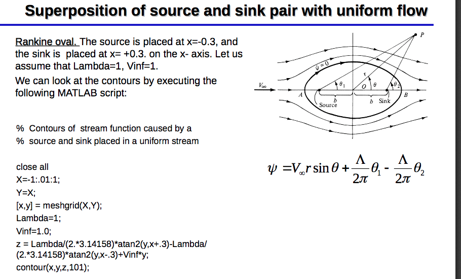
For comparison, I also plotted horizontal Rankine Oval. Please, see the picture. I don't understand what are these horizontal lines on inclined Rankine Oval. And how I get rid of them?

5 Kommentare
darova
am 22 Apr. 2020
Do you have the picture of expected result? Try surf to see how it looks


tag
am 22 Apr. 2020
I don't have a picture unfortunately, I just need inclined Rankine Ovale which is flowed round by inclined stream (at the same angle). Just like in case of horizontal Rankine Ovale (see picture for example) but picture turned at some angle.

Also, my picture is 2D, how can I use surf?
darova
am 22 Apr. 2020
I found this
tag
am 22 Apr. 2020
I know, I can plot horizontal Oval with horizontal stream without a problem. But when I try to plot inclined Oval with inclined stream there is a problem.

Omer
am 15 Okt. 2022
Can u send me the code for the horizontal one?
Akzeptierte Antwort
David Goodmanson
am 22 Apr. 2020
Bearbeitet: David Goodmanson
am 22 Apr. 2020
Hi tag,
Atan2 is restricted to -pi < atan <= pi, so when the angle increases past pi you get a jump down to -pi That occurs when x is negative and y passes through 0 on the negative x axis. If you consider x and y as z = x + iy in the complex plane, those lines are branch cuts and Matlab is doing a good job of showing them.
When both points have the same y value, the branch cuts cancel out to the left of the second point and you don't see any discontinuity there. (The branch cut remains in between the two points). With different y values you see both branch cuts.
A good way to get out of this is to go to complex notation. The psi2 calculation below puts the original code into the complex domain. The angle function does basically the same thing as atan2, so by using two angle functions psi2 comes out the same as psi1.
The psi3 version divides two complex functions to find the difference in angle between the the two of them, then finds that angle. This effectively allows the two branch cuts to cancel, and the resulting plot has no discontinuities, except on the line between the two points.
[x,y] = meshgrid(-25:0.1:25);
m=5;
%a=2;
U=1;
p1 = [3 -8];
p2 = [7 -4];
psi1 = U*(y*cos(pi/4)-x*sin(pi/4))-m*atan2(y-p2(2),x-p2(1))+m*atan2(y-p1(2),x-p1(1));
figure(1)
contour(x,y,psi1,100); % original result
colorbar
grid on;
z = x+i*y;
z1 = p1(1) + i*p1(2);
z2 = p2(1) + i*p2(2);
u = (z2-z1)/abs(z2-z1); % direction vector on the unit circle
psi2 = imag(z/u) -m*angle(z-z2) + m*angle(z-z1);
figure(2)
contour(x,y,psi2,100); % same result
colorbar
grid on;
psi3 = imag(z/u) -m*angle((z-z2)./(z-z1));
figure(3)
contour(x,y,psi3,100); % new result
colorbar
grid on;
5 Kommentare
David Goodmanson
am 23 Apr. 2020
what version of Matlab are you using? I copied the code here back, and get the oval in fig 3, without the branch cuts.
tag
am 23 Apr. 2020
I'm using 2015b. Сould this be the reason? Please, see my result pictures and code from your answer I'm using.


David Goodmanson
am 23 Apr. 2020
Bearbeitet: David Goodmanson
am 23 Apr. 2020
I don't see how that could make a difference. For me, plots 1 and 2 are identical because phi1 and phi2 are identical, within 1e-15 or values like that. So that is the first thing to check. Have you possibly, earlier on, assigned to 'i' a value different than sqrt(-1) ? Although I think it's kind of ugly notation, one way to guard against that is to replace i with 1i in the definition of z1 and z2.
tag
am 23 Apr. 2020
Weitere Antworten (1)
darova
am 22 Apr. 2020
Here is a formula
And this is how surface looks like originally

Here is the problem part


My suggestion is to plot only half of the data (y = 0 .. 1)


Actually smaller half to get rid of center part


And then use contour with levels
contour(x,y,z,-1:.1:0)

1 Kommentar
tag
am 23 Apr. 2020
Kategorien
Mehr zu 2-D and 3-D Plots finden Sie in Hilfe-Center und File Exchange
Produkte
Community Treasure Hunt
Find the treasures in MATLAB Central and discover how the community can help you!
Start Hunting!
Translated by ![]()