CCSDS TM HDL Receiver
This example shows how to use a Consultative Committee for Space Data[ Systems (CCSDS) Telemetry (TM) receiver developed using Simulink®. The Simulink blocks used in this example are optimized for HDL code generation and hardware implementation. This example supports coding and modulation schemes according to the following standards:
Introduction
The CCSDS TM receiver in this example supports the binary phase shift keying (BPSK) and quadrature phase shift keying (QPSK) modulation types. For channel coding, the receiver supports convolutional code with a rate of 1/2, RS codes and concatenation of RS codes and convolutional code with a rate of 1/2. The receiver implements symbol timing synchronization and carrier frequency synchronization, which are essential in a single-carrier communication system. The default symbol rate is 2 Msps. The sample rate must be four times the symbol rate. These specifications vary based on the symbol rate.
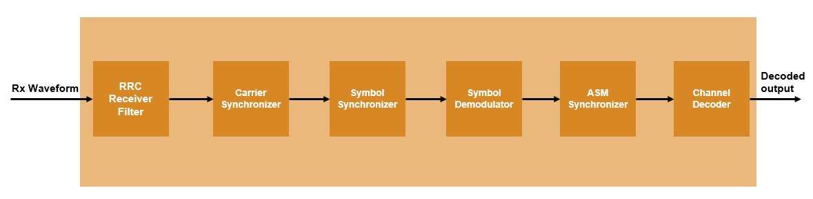
This figure shows the block diagram of the CCSDS TM Receiver. The receiver samples the received signal at a specified sample rate. The RRC Receive Filter block performs matched filtering on the received waveform. The Carrier Synchronizer and Symbol Synchronizer blocks perform synchronization operations and generate symbols. The Symbol Demodulator block demodulates these symbols to soft LLRs. The Attached Sync Marker (ASM) block performs the frame synchronization along with the phase ambiguity resolution on these LLR values. Finally, the Channel Decoder block decodes the synchronized symbols and provides the decoded bits as output.
File Structure
The example contains these Simulink models and MATLAB® scripts.
ccsdsTMReceiver— Model that comprises the CCSDS TM receiver.runCCSDSTMReceiver— Script that runs and verifies theccsdsTMReceivermodel.generateRxInputWaveform— Script that generates receiver inputs.ccsdsTMReceiverSimulink— Script that assigns the variable to base workspace and runs theccsdsTMReceivermodel.ccsdsTMReceiverParameters— Script that generates parameters for theCCSDS TM Receiversubsystem required for initialization.
Model Architecture
This figure shows the structure of the ccsdsTMReceiver model. The top level of the model reads signals from the MATLAB® base workspace, passes them to the CCSDS TM Receiver subsystem, and then writes the outputs back to the workspace. Use the runCCSDSTMReceiver script to run the model and postprocess the outputs.
Modelname  = 'ccsdsTMReceiver';
open_system(Modelname);

Input Ports
rxDataIn — Input data, specified as 16-bit complex data.
rxValidIn — Control signal to validate the rxDataIn, specified as a Boolean scalar.
reset — Reset signal, specified as a Boolean scalar.
Output Ports
dataOut — Decoded output data bits, returned as a Boolean scalar.
validOut — Control signal to validate the dataOut, returned as a Boolean scalar.
normFreqOffset — Estimated normalized frequency offset.
RRC Receive Filter
The RRC Receive Filter is a Discrete FIR Filter block with matched filter coefficients used for pulse-shaping in the transmitted waveform. The RRC matched filtering generates an RC pulse-shaped waveform, which has zero signal interference characteristics at maximum eye opening in the eye diagram of the waveform. Also, the matched filtering process maximizes the signal-to-noise power ratio (SNR) of the filter output.
Carrier Synchronizer
The Carrier Synchronizer subsystem is a TYPE II PLL with a sinusoidal phase error detector, which operates at a 45 – degree operating point. The phase error detector is described in Chapter 7.2.2, and the design equations are described in the Appendix C of [ 4 ]. A detailed analysis of a TYPE II PLL with a zero operating point sinusoidal phase detector is described in Chapter 4 of [ 5 ]. The sign function of the phase detector in the real and imaginary parts converts all of the angles in the four quadrants into a first-quadrant angle (0 to 90 degrees), which creates an ambiguity of 90, 180, 270 degrees for the second (90 to 180 degrees), third (–180 to –90 degrees) and fourth (–90 to 0 degrees) quadrant angles, respectively. The phase error is calculated as a deviation from the operating point (45 degrees) of the phase detector. The proportional plus integrator filter in the Loop Filter subsystem filters the phase error. The loop filter sets the normalized loop bandwidth (normalized by the sample rate) and the loop damping factor. The default normalized loop bandwidth is set to 0.007, and the default damping factor is set to 0.7071. The filtered error is given as a phase increment source to the NCO block for complex exponential phase generation. The complex exponential phase is used to correct the frequency and phase of the input. A detailed analysis of direct digital synthesis is described in Chapter 9.2.2 of [ 4 ].
open_system([Modelname '/CCSDS TM Receiver/Carrier Synchronizer']);
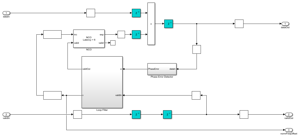
The Carrier Synchronizer subsystem estimates the normalized frequency within the symbol rate range of –0.005 to 0.005, equivalent to a frequency offset range of –10 KHz to 10 KHz for a symbol rate of 2 Mbaud.
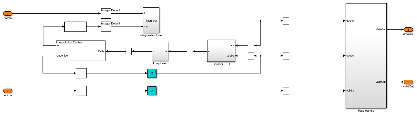
Symbol Synchronizer
The Symbol Synchronizer subsystem is a PLL-based implementation. This subsystem generates samples at an optimum time instant (maximum eye opening instant), as described in Chapter 8.5 of [ 4 ]. The subsystem generates one output sample for every four input samples. The Interpolation Filter subsystem implements a piecewise parabolic interpolator with a hardware-resource-efficient farrow structure as described in Chapter 8.4.2, and the farrow coefficients are tabulated in Table 8.4.1 of [ 4 ] (the free parameter  of the coefficients is taken as 0.5). This filter introduces fractional delays in the input waveform. The
 Gardner TED subsystem implements a Gardner timing error detector as described in Chapter 8.4.1 of [ 4 ]. The Loop filter subsystem filters the timing error and passes it to the Interpolation Control MATLAB function block. This block implements a mod-1 decrementing counter to calculate fractional delays based on the loop filtered timing error as described in Chapter 8.4.3 of [ 4 ] to generate interpolants at optimum sampling instants. The Rate Handle subsystem selects the required interpolant indicated by the strobe. This sample corresponds to the maximum eye opening of the eye diagram before symbol synchronization.
open_system([Modelname '/CCSDS TM Receiver/Symbol Synchronizer']);
Symbol Demodulator
The Symbol Demodulator subsystem demodulates the synchronized symbols based on the modulation scheme. This subsystem uses the Variant Subsystem to select either a BPSK Symbol Demodulator or QPSK Symbol Demodulator based on the specified modulation scheme.
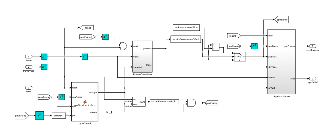
ASM Synchronizer
The ASM Synchronizer subsystem performs the frame synchronization and resolves phase ambiguity. Within this subsystem, the Frame Correlation subsystem correlates the demodulated symbols with sequences corresponding to the original ASM, introducing phase ambiguity. The Frame Correlation subsystem provides the highest correlation peak and phase ambiguity. The Synchronization subsystem use this correlation to achieve frame synchronization and subsequently resolves the phase ambiguity across the complete set of demodulated symbols. For more details on the correlation process, see section 9.3.7 in [ 3 ]. The ASM Synchronizer subsystem uses the Variant Subsystem to select either a BPSK ASM Synchronizer or QPSK ASM Synchronizer based on the specified modulation scheme.
Channel Decoder
The Channel Decoder subsystem decodes the ASM-synchronized demodulated symbols. The Channel Decoder subsystem uses the Variant Subsystem to select either a Channel Decoder Viterbi, Channel Decoder RS or a Channel Decoder Concatenated subsystem based on the specified channel coding.
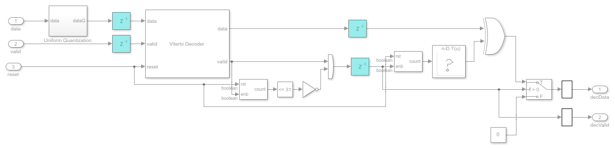
Convolutional Decoder
The demodulated symbols synchronized with ASM are quantized to an 8-bit word length and provided as input to the Viterbi Decoder block. Following this, ASM is removed from the output of the Viterbi Decoder block and then randomized using a sequence calculated based on transferFrameLength. Randomized bits are provided as the output of the Channel Decoder.
open_system([Modelname '/CCSDS TM Receiver/Channel Decoder/Convolutional Decoder']);
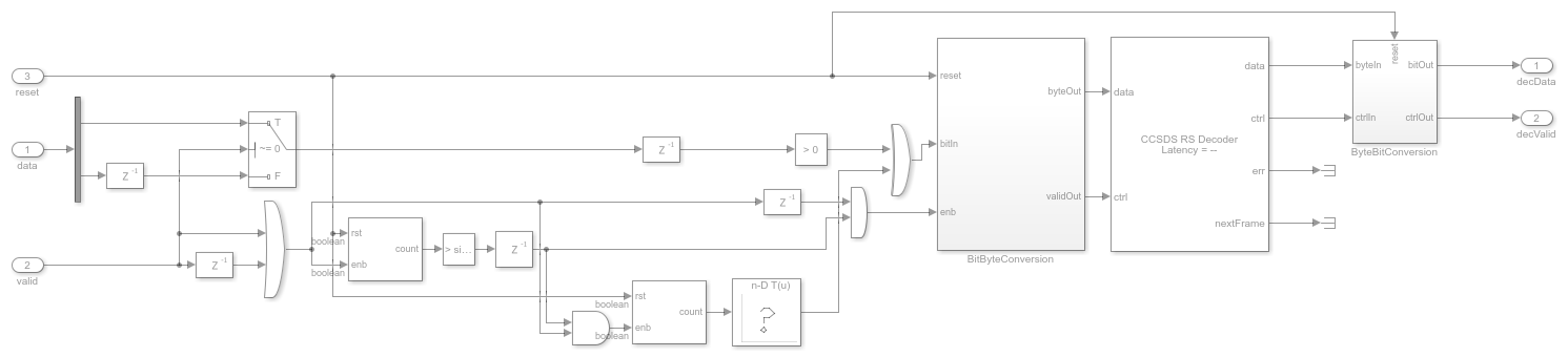
RS Decoder
The ASM synchronized demodulated bits are randomized with a sequence calculated based on transferFrameLength. Randomized bits are converted to bytes and provided as input to the Viterbi Decoder block. Output bytes are converted back to bits and provided as output of the Channel Decoder.
open_system([Modelname '/CCSDS TM Receiver/Channel Decoder/RS Decoder']);
Concatenated RS Decoder
The ASM synchronized demodulated symbols are quantized to a word length of 8 bits and provided as input to the Viterbi Decoder block. ASM is removed from the output of the Viterbi Decoder block and randomized with a sequence calculated based on transferFrameLength. Randomized bits are converted to bytes and provided as input to the Viterbi Decoder. Output bytes are converted back to bits and provided as output of the Channel Decoder.
open_system([Modelname '/CCSDS TM Receiver/Channel Decoder/Concatenated RS Decoder']);

close_system(Modelname,0);
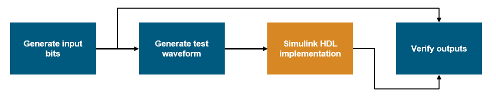
Simulation Setup
The block diagram shows the simulation setup of this example, which is implemented in the runCCSDSTMReceiver script. The script contains Satellite Communications Toolbox functions to generate a test waveform, which is provided as input to the ccsdsTMReceiver model. Output signals from receiver are compared with input bits.
Simulation
Use the runCCSDSTMReceiver script to run the simulation and verify the results. The script displays its progress in the MATLAB command window.
load_system(Modelname);              % Load Simulink model
open_system([Modelname '/Control Scope']);

runCCSDSTMReceiver;
Selected Transmission parameters:

          channelCoding: "convolutional"
    transferFrameLength: 100
              modScheme: "QPSK"
                  alpha: 0.3500
                    sps: 4
                NFrames: 100

Generate input data bits for transmitter

Generate test waveform

Running ccsdsTMReceiver.slx
...................
Simulation completed

Verification results:

Initial frames not compared: 30
Number of bits errored = 0 out of 52800

Further Exploration
You can modify the transmitter parameters transferFrameLength, modScheme, alpha, NumFrames, and fSym. You can also modify the channel conditions by tuning the chParams variable.
Generate HDL Code
To generate HDL code for this example, you must have an HDL Coder™ license. Use the makehdl and makehdltb commands to generate HDL code and an HDL test bench for the ccsdsTMReceiver/CCSDS TM Receiver subsystem. You can synthesize the generated HDL code and target on the Xilinx® Zynq®-7000 ZC706 evaluation board. The table shows the post place and route resource utilization results for QPSK modulation type.
F = table(...
    categorical({'Slice LUTs'; 'Slice Registers';'RAMB36'; 'RAMB18'; ...
    'DSP48';'FMax(Mhz)'}),...
    categorical({'19851';'17170'; '3'; '0'; '70';'193.5'}),...
    categorical({'34031'; '27571'; '28'; '1'; '60';'136.66'}),...
    categorical({'43005'; '34438'; '29'; '1'; '60';'135.44'}),...
    'VariableNames',...
    {'Resources','Convolutional QPSK Rx Usage',...
    'RS QPSK Rx Usage',...
    'Concatenated QPSK Rx Usage'});

disp(F);

close_system(Modelname,0);
       Resources       Convolutional QPSK Rx Usage    RS QPSK Rx Usage    Concatenated QPSK Rx Usage
    _______________    ___________________________    ________________    __________________________

    Slice LUTs                    19851                    34031                    43005
    Slice Registers               17170                    27571                    34438
    RAMB36                        3                        28                       29
    RAMB18                        0                        1                        1
    DSP48                         70                       60                       60
    FMax(Mhz)                     193.5                    136.66                   135.44
References
[1] TM Synchronization and Channel Coding. Recommendation for Space Data System Standards, CCSDS 131.0-B-3. Blue Book. Issue 3. Washington, D.C.: CCSDS, September 2017.
[2] Radio Frequency and Modulation Systems--Part 1: Earth Stations and Spacecraft. Recommendation for Space Data System Standards, CCSDS 401.0-B-30. Blue Book. Issue 30. Washington, D.C.: CCSDS, February 2020.
[3] TM Synchronization and Channel Coding - Summary of Concept and Rationale. Report Concerning Space Data System Standards, CCSDS 130.1-G-3. Green Book. Issue 3. Washington, D.C.: CCSDS, June 2020.
[4] Rice, Michael. Digital Communications: A Discrete-Time Approach. Upper Saddle River, N.J: Pearson/Prentice Hall, 2009.
[5] Gardner, Floyd M. Phaselock Techniques: Gardner/Phaselock Techniques. Hoboken, NJ, USA: John Wiley & Sons, Inc., 2005.