Send and Receive Double-Lane Change Scene Data
This example shows you how to use the Simulation 3D Message Set and Simulation 3D Message Get blocks to communicate with the 3D visualization environment when you run the double-lane change maneuver. Specifically, you use the:
Simulation 3D Message Get block to retrieve which barrels the vehicle hits during the maneuver.
Simulation 3D Message Set block to control the traffic signal light.
For the minimum hardware required to run the example, see the Unreal Engine Simulation Environment Requirements and Limitations.
Run a Double-Lane Change Maneuver
With the 3D visualization environment enabled, run a double-lane change maneuver.
Create and open a working copy of the double-lane change reference application project.
Enable the 3D visualization environment. In the Visualization subsystem, open the 3D Engine block mask and select Enabled. Apply the changes and save the model.
Alternatively, at the MATLAB® command prompt, enter this code.
Run the maneuver for 25 seconds. View the simulation in the Simulation 3D Viewer. As the vehicle completes the maneuver, it hits the barrel.
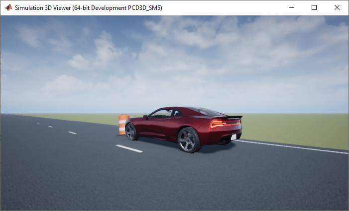
Use Simulation 3D Message Get Block to Retrieve Barrel Data
Use the Simulation 3D Message Get block to retrieve which barrels the vehicle hits during the maneuver. By default, the maneuver uses the double-lane change scene.
Navigate to the Visualization > 3D Engine subsystem. Right-click the 3D Engine block and select Mask > Look Under Mask. In the Visualization > 3D Engine > 3D Engine subsystem, insert these blocks:
Simulation 3D Message Get
Display
Set the Simulation 3D Message Get block parameters so that the block retrieves barrel data from the double-lane change scene. Set these block parameters, apply the changes, and save the model.
Signal name, SigName to
NumOfBarricadesHitData type, DataType to
booleanMessage size, MsgSize to
[1
                                    8]
Sample time to
-1
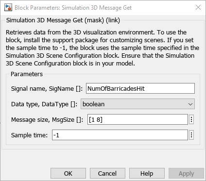
Alternatively, at the MATLAB command prompt, enter this code.
Connect the Simulation 3D Message Get and Display blocks as shown. Confirm the block parameters. Save the model.

Verify that the Simulation 3D Scene Configuration block executes before the Simulation 3D Message Get block. That way, the Unreal Engine® 3D visualization environment prepares the data before the Simulation 3D Message Get block receives it. To check the block execution order, right-click the blocks and select Properties. On the General tab, confirm these Priority settings:
Simulation 3D Scene Configuration —
0Simulation 3D Message Get —
1
For more information about execution order, see Control and Display Execution Order.
Run the maneuver. As the simulation runs, the display block updates with the
ReadMsgboolean value1when the vehicle hits the corresponding barrel.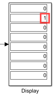
The results indicate that the vehicle hits
Drum01Node67at the end of the maneuver.This table provides the Double Lane Change scene barrel name that corresponds to the
ReadMsgarray element.Simulation 3D Message Get Block
ReadMsgValueUnreal® Editor Barrel Name
ReadMsg(1,1)Drum01NodeReadMsg(1,2)Drum01Node67ReadMsg(1,3)Drum01Node68ReadMsg(1,4)Drum01Node69ReadMsg(1,5)Drum01Node70ReadMsg(1,6)Drum01Node71ReadMsg(1,7)Drum01Node72ReadMsg(1,8)Drum01Node73
Use Simulation 3D Message Set Block to Control Traffic Signal Light
Start the maneuver at 5 seconds. In the Lane Change Reference Generator block, set Maneuver start time to
5.Navigate to the Visualization > 3D Engine subsystem. Right-click the 3D Engine block and select Mask > Look Under Mask. In the Visualization > 3D Engine > 3D Engine subsystem, insert these blocks:
Simulation 3D Message Set
Repeating Sequence Stair
Set the Simulation 3D Message Set block parameters so that the block sends traffic signal data to the double-lane change scene. Set these block parameters, apply the changes, and save the model.
Signal name, SigName to
TrafficLight1Sample time to
-1
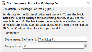
This table provides the scene traffic signal light color that corresponds to the
WriteMsgvalue in the Double Lane Change scene.Simulation 3D Message Set Block
WriteMsgValueTrafficLight1Color0Red1Yellow2GreenAlternatively, at the MATLAB command prompt, enter this code.
Set the Repeating Sequence Stair block parameters to send a command that corresponds to red, yellow, and green traffic light signals. Set these block parameters, apply the changes, and save the model.
Vector of output values: to
[0 0 0 1
                                    1 2 2 2 2 2 2 2 2 2 2 2 2 2 2 2 2 2 2 2 2 2 2 2 2
                                2].'
Sample time to
1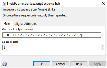
Output data type to
int32
Alternatively, at the MATLAB command prompt, enter this code. Apply the block changes and save the model.
Connect the blocks as shown. Confirm the block parameters and signal connections. Save the model.

Verify that the Simulation 3D Message Set block executes before the Simulation 3D Scene Configuration block. That way, Simulation 3D Message Set prepares the signal data before the Unreal Engine 3D visualization environment receives it. To check the block execution order, right-click the blocks and select Properties. On the General tab, confirm these Priority settings:
Simulation 3D Scene Configuration —
0Simulation 3D Message Set —
-1
For more information about execution order, see Control and Display Execution Order.
Run the maneuver. As the simulation runs, in the Simulation 3D Viewer, you can see the
TrafficLight1light change from red to yellow to green.
Time Range (s)
WriteMsgValueTrafficLight1Color0–3
0Red3–5
1Yellow5–30
2Green
See Also
Double Lane Change | Simulation 3D Message Get | Simulation 3D Message Set | 3D Engine | Simulation 3D Scene Configuration
