Generate ePWM Waveform for Specified Frequency and Duty Cycle
This example shows how to generate an ePWM waveform for the specified frequency and duty cycle using time-base, counter compare and action qualifier submodules.
In this example, you learn how to:
Generate ePWM waveforms for the specified frequency in up-count and up-down counting modes of operation.
Achieve required duty cycle.
Prerequisites
Complete the following tutorial:
Required Hardware
TI Delfino F28379D LaunchPad
Hardware Connection
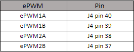
You can view the ePWM waveforms in an oscilloscope at the following pins in the F28379D LaunchPad hardware.
Available Model
f2837xePWMGettingStarted.slx
Model
Open the f2837xePWMGettingStarted.slx model.

ePWM1 is configured to generate waveforms of frequency of 10 kHz.
ePWM2 is configured to generate waveforms of frequency of 20 kHz.
Configure Model
1. Open the model. The model in this example is configured for the TI Delfino F28379D LaunchPad hardware.
2. To run the model on other TI C2000 processors, press Ctrl+E to open the Configuration Parameters dialog box. Then select a hardware board by navigating to Hardware Implementation > Hardware board.
3. Set the desired ePWM frequency by navigating to Target Hardware Resources > ePWM. Click Apply and then OK.
Frequency and Duty Cycle Calculations
1. In this example, the frequency of the ePWM clock based on the configuration setting Sysclk/2 is 100 MHz.
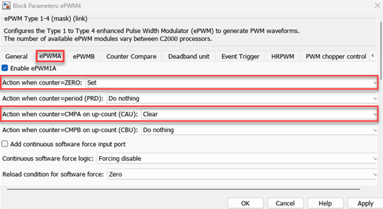
2. ePWM1 output is configured to get an output waveform of frequency of 10 kHz. This is achieved by the following configurations on the ePWM Type 1-4 block:


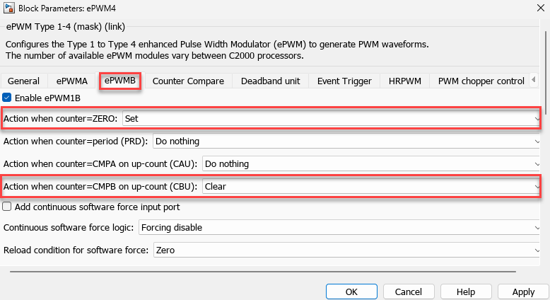
4. ePWMA waveform is generated through the CMPA action and ePWMB waveform is generated through the CMPB action. Based on this action qualifier configuration, for a duty cycle of 25%, the CMPA value is 25% of TBPRD and, for a duty cycle of 75%, the CMPB value is 75% of TBPRD.
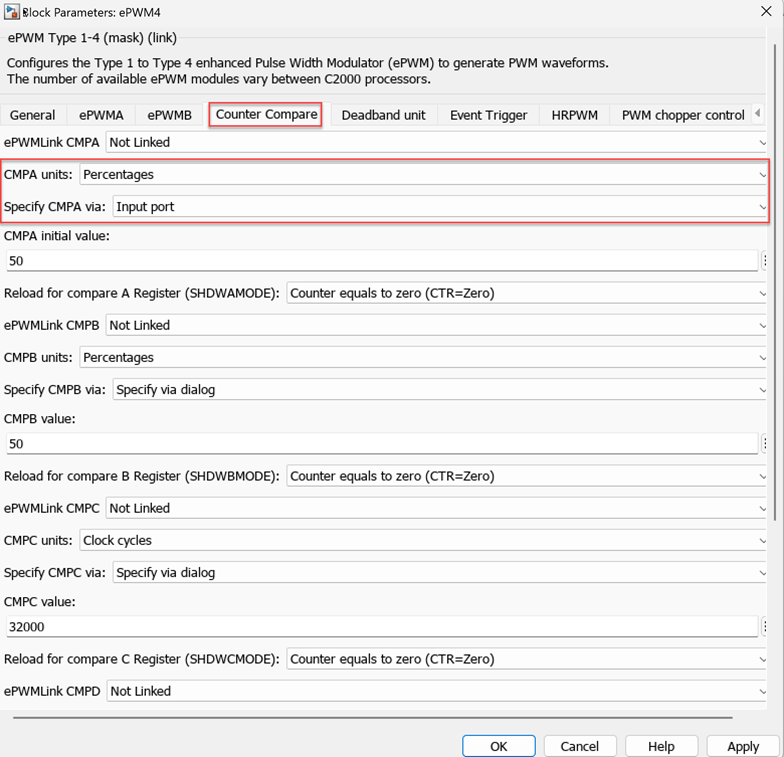
5. The configuration in this image achieves 20 kHz output frequency for ePWM2. As the ePWM2 is configured for the up-down mode, the period is half of the desired frequency.
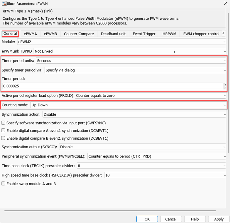
For more information about counting modes of a timer period, see Timer period.
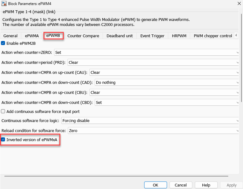
6. With the default action qualifier settings shown in this image, the desired duty cycle for ePWM2A is provided through an input port and in percentage.
7. Select ePWM2B as the inverted version of ePWM2A as shown here.
Run Model
1. Click Build, Deploy & Start under Hardware tab or press Ctrl+B to build and download the executable file on the target.
2. Connect the oscillator to J4 pins 37-40.
3. Observe the following ePWM waveforms:
ePWM1A at GPIO0 (J4 pin 40) is a 1 kHz signal with 25% duty cycle.
ePWM1B at GPIO1 (J4 pin 39) is a 1 kHz signal with 75% duty cycle.
ePWM2A at GPIO2 (J4 pin 38) is a 20 kHz signal with 50% duty cycle.
ePWM2B at GPIO3 (J4 pin 37) is the inverted version of ePWM2A.
Other Things to Try
Alternatively, you can capture the ePWM signal using the eCAP block and view the signal using a Scope block.
Try generating waveforms for different frequencies and duty cycles.
Try generating waveforms in the down-count mode of operation.