Deploy and Interact with Generated Executable Programs on Custom STM32 Target Hardware Boards
This example shows how you can deploy executable programs generated from Simulink models to custom target hardware boards that include an STM32 Microcontroller. For example, a custom board might be designed to meet compact space requirements or to provide pinouts or capabilities that are not provided on boards such as the STMicroelectronics Discovery and Nucleo boards. This example also shows, once a program is deployed, how you can interact with the program as it runs on the target hardware to debug it, monitor signals, and tune parameters.
The approach that you take to deploy a generated executable program to a custom board and debug, monitor signals, and tune parameters while the program runs on the target hardware depends on:
What hardware interfaces are on the board
What COM port connectors are on the board
Whether there is an onboard UART bootloader on the board
Whether you have access to an STLink-V3SET debugging and programming probe
This example provides the model STLinkExtMode.slx and the generated STM32CubeMX project IO configuration file UsingSTLinkForProcessors/UsingSTLinkForProcessors.ioc, which you can use to test a workflow for deploying to a custom target. The .ioc file contains configuration settings for the microcontroller, pin assignments, clock, and peripheral devices.
Deploy Executable Program to STM32 Microcontroller By Using STLink-V3SET Debugger/Programmer
The STLink-V3SET debugging and programming probe supports JTAG and SWD protocols for interfacing with an STM32 Microcontroller. To use the STLink-V3SET Debugger/Programmer to deploy an executable program generated from a Simulink model to a custom board, do the following:
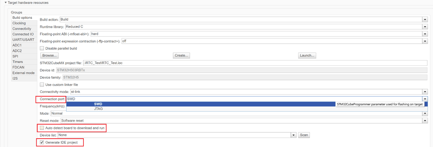
1. Select model configuration parameter Generate IDE project. When you select this parameter, Simulink generates an Simulink project based on the integrated development environment (IDE) configured for your model.
2. When you configure the target hardware resources for a model, specify whether you are going to deploy the generated program to flash memory by using the SWD or JTAG protocol. Set model configuration parameter Connection port to SWD or JTAG.
3. Determine the type of cable that you need to connect the SWD or JTAG flash connector on your custom board to your STLink-V3SET debug connector. The debug pin that is on the flash connector port on the custom board determines the cable that you need. This table lists available STLLink-V3SET debug connectors for the two types of flash connection ports.
Flash Connection Port | STLink-V3SET Debug Connectors |
SWD | CN1, CN2, CN6 |
JTAG | CN1, CN2 |
4. Connect the SWD/JTAG connector to the STLINK-V3SET debug connector.
5. Power on the custom board and ST-Link-V3SET probe. Make sure that the grounds of both are common. You can also power the microcontroller by from ST-Link (5v and Gnd)
6. Clear model configuration parameter Auto detect board to download and run.
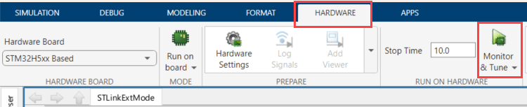
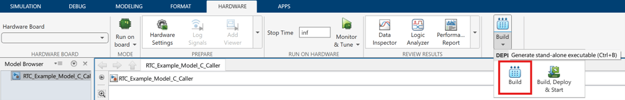
7. Go to Hardware tab and click Build. The code generator produces a .hex, .elf, or .bin file.
8. Use the STLink-V3 SET probe to deploy the generated executable program to the STM32 Microcontroller. In the STM32CubeProgrammer, click Connect. A dialog box appears indicating whether a connection is established. If an error occurs, see https://community.st.com/t5/stm32-mcus/how-can-i-connect-to-my-stm32-evaluation-board-using/ta-p/49554.
Deploy Executable Program to STM32 Microcontroller Over Serial Connection By Using STM32CubeProgrammer and SWD or JTAG Protocol
You can deploy an executable program ( hex, .elf, or .bin file) generated from a Simulink model to flash memory of an STM32 Microcontroller by using the STM32CubeProgrammer and the SWD or JTAG debug protocol. Once the ELF file is deployed on the target, you can debug the code using keil/stm32CubeIDE. For more information, see Debug Simulink Generated Code using STM32CubeIDE.
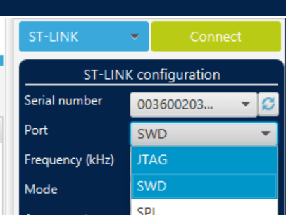
1. From your development computer, in the STM32CubeProgrammer dialog box, click ST-LINK. An ST-LINK configuration panel appears.
2. In the ST-LINK configuration panel, based on your target hardware setup, set Port to JTAG or SWD.
3. Establish a connection between the development computer and the target STM32 Microcontroller and load the executable program into flash memory. In the STM32CubeProgrammer, click Connect. A dialog box appears indicating whether a connection is established. If an error occurs, see https://community.st.com/t5/stm32-mcus/how-can-i-connect-to-my-stm32-evaluation-board-using/ta-p/49554.
Flash Custom STM32 Board Using UART Bootloader
Deploy an executable program generated from a Simulink® model to the flash memory of a custom STM32® board by using STM32CubeProgrammer and the onboard UART bootloader.
1. In the Simulink model, on the Hardware tab, click Build to generate an executable file (.hex, .elf, or .bin), and locate the file in the build folder.
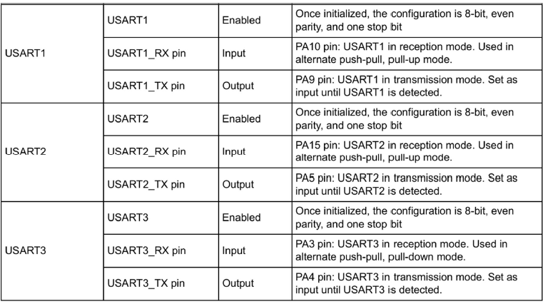
2. Refer to AN2606: Introduction to system memory boot mode on STM32 MCUs to identify UART peripherals supported by the bootloader and the corresponding RX and TX pins for your target device. For example, STM32H503xx devices support UART1, UART2, and UART3 for bootloader-based flashing.
3. Power off the STM32 board and the USB-to-FTDI adapter.
4. Configure the boot pins to enable UART boot mode. For STM32H503xx devices, pull the BOOT0 pin high to VCC.
5. Connect the USB-to-FTDI adapter to the STM32 board:
Connect FTDI
TXto the STM32 UARTRXpin.Connect FTDI
RXto the STM32 UARTTXpin.Connect FTDI ground to the STM32 board.
Power the STM32 board using either an external supply or the FTDI adapter, and ensure all grounds are common.
6. Connect the USB-to-FTDI adapter to the development computer and power on the STM32 board.
7. Open STM32CubeProgrammer and set the connection type to UART.
8. Select the appropriate COM port and baud rate, then click Connect. STM32CubeProgrammer automatically sends the required boot pattern and waits for acknowledgment from the device.
9. Verify that the log window indicates a successful connection.
10. In STM32CubeProgrammer, open the Erasing and Programming section, specify the path to the generated executable file, and click Start Programming.
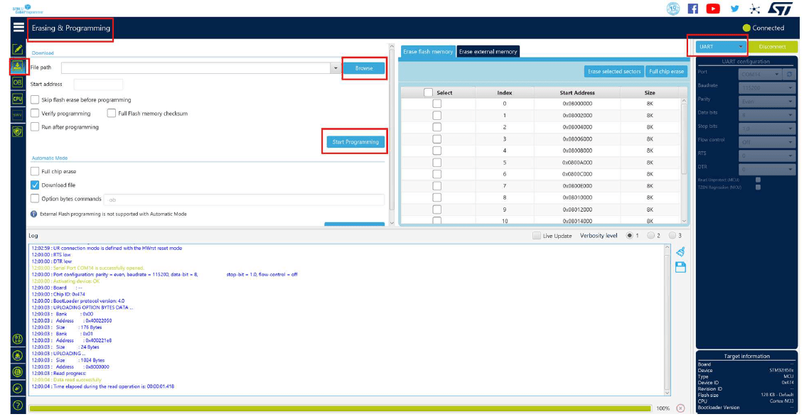
11. Confirm that the log window reports file download complete, then click Disconnect to end the session.
Monitor Signals and Tune Parameters By Using Simulink External Mode and STLink-V3SET Probe or FTDI Chip
By using an STLink-V3SET profiler or an FTDI chip, you can use serial communication to monitor signals and tune parameters represented in a generated executable program as it runs on a custom STM32 board under either of these conditions:
When the custom board does not have an onboard STLink in-circuit debugger and programmer
You want to use a USART or UART peripheral that is not supported by the onboard STLink device
The STLink-V3SET or FTDI device acts as a virtual COM port for a USART or UART peripheral.
To use the STLink-V3SET or FTDI device for external mode simulations:
1. Connect the STLink-V3SET or FTDI device transmit (TX) and receive (RX) pins to the corresponding pins on the USART or UART connector on the STM32 board. This table lists board types with the connectors that are available for the virtual COM port.
Board Type | Connectors for Virtual COM Port |
MB1440 | CN1, CN3 |
MB1441 | CN1 |
2. Select model configuration parameter External mode.
3. Set the connectivity model configuration parameters USART/UART and Serial port to values for the USART or UART module on the STM32 board.
4. Follow the steps provided in Serial Configuration for Monitor & Tune and PIL for STM32 Processor-Based Boards to complete the setup for using external mode for signal monitoring and parameter tuning over a serial connection.