Control Indicator Lamp Dimmer Using Variant Conditions
This example shows how to use variant transitions to model multiple designs in a single Stateflow® chart. Each variant transition leads to a state that represents a variant configuration for your system. When you generate code from the chart, you can select which variant configuration you want to use. By default, the generated code only contains the code and data needed to execute the variant configuration you select.
Variant Configurations for Lamp Control System
In this example, a Stateflow chart models a control system for a lamp. The chart uses variant configurations to combine three possible lamp designs.
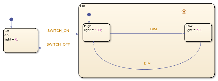
The simplest design consists of a lamp with a single on-off switch. To model this design, you can create a Stateflow chart with two states, Off and On, that set the value of the chart output light to 0 or 100, respectively. The chart transitions between these states when it receives the input events SWITCH_ON and SWITCH_OFF.

A more advanced lamp design includes a dimmer with two settings, high and low. To model this lamp design, you can add two substates to the state On. When the lamp is on, the substates High and Low set the value of the chart output light to 100 or 50, respectively. The input event DIM triggers the transition between these substates.
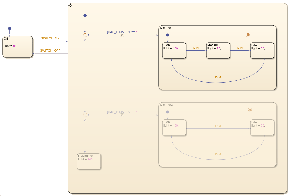
Finally, the third design uses a dimmer with three settings, high, medium, and low. In a chart that models this design, the state On contains three substates that set the value of the chart output light to 100, 75, or 50, respectively. The input event DIM triggers the transition from High to Medium, from Medium to Low, and from Low to High.

This example combines these designs into a single Stateflow chart. In the state On, the substates Dimmer1, Dimmer2, and NoDimmer represent the variant configurations for the system. A pair of variant transitions evaluate the parameters HAS_DIMMER1 and HAS_DIMMER2 and guard the entry into each of these substates.
![]()
When you simulate, compile, or generate code from the model, the conditions on the variant transitions determine which variant configuration is active. The portions of the chart that correspond to inactive variant configurations appear dimmed on the Stateflow canvas. For instance, in this chart, the variant configuration with three dimmer settings is active.
To change which variant configuration is currently active, modify the guarding parameters in the base workspace and update the model.
Generate Code for Variant Configurations
To generate code from your Stateflow chart, you must have Simulink® Coder™ or Embedded Coder®. By default, the generated code only contains the code and data for the active variant configuration. For example, if you select the variant configuration with three dimmer settings, the generated code defines these constants:
/* Named constants for Chart: '<Root>/Lamp' */
#define sfVariantLam_IN_NO_ACTIVE_CHILD ((uint8_T)0U)
#define sfVariantLampE_event_SWITCH_OFF (1)
#define sfVariantLampEx_event_SWITCH_ON (2)
#define sfVariantLampExample_IN_High   ((uint8_T)1U)
#define sfVariantLampExample_IN_Low    ((uint8_T)2U)
#define sfVariantLampExample_IN_Medium ((uint8_T)3U)
#define sfVariantLampExample_IN_Off    ((uint8_T)1U)
#define sfVariantLampExample_IN_On     ((uint8_T)2U)
#define sfVariantLampExample_event_DIM (0)
If you are using Embedded Coder, you can include preprocessor conditional #if statements in your generated code by enabling the chart property Variant activation time. For example, if you enable this chart property, the generated code defines these constants regardless of which variant configuration is active:
/* Named constants for Chart: '<Root>/Lamp' */
#if HAS_DIMMER1 == 1 || HAS_DIMMER2 == 1
#define sfVariantLam_IN_NO_ACTIVE_CHILD ((uint8_T)0U)
#endif
#define sfVariantLampE_event_SWITCH_OFF (1)
#define sfVariantLampEx_event_SWITCH_ON (2)
#if HAS_DIMMER1 == 1 || HAS_DIMMER2 == 1
#define sfVariantLampExample_IN_High   ((uint8_T)1U)
#endif
#if HAS_DIMMER1 == 1 || HAS_DIMMER2 == 1
#define sfVariantLampExample_IN_Low    ((uint8_T)2U)
#endif
#if HAS_DIMMER1 == 1
#define sfVariantLampExample_IN_Medium ((uint8_T)3U)
#endif
#define sfVariantLampExample_IN_Off    ((uint8_T)1U)
#define sfVariantLampExample_IN_On     ((uint8_T)2U)
#define sfVariantLampExample_event_DIM (0)
For more information about generating code, see Generate Code Using Simulink Coder (Simulink Coder) and Generate Code Using Embedded Coder (Embedded Coder).
Manage Variant Configurations with the Variant Manager
The Variant Manager allows you to manage variant configurations in your model. To open the Variant Manager, on the Modeling tab, under Design Data, select Variant Manager.

For more information about how to use the Variant Manager, see Variant Manager for Simulink (Simulink).
Guidelines for Using Variant Transitions
To model several system designs in a single chart, represent each variant configuration with one or more states connected by variant transitions. Follow these guidelines:
In the transition path to each variant configuration, you can combine variant transitions or transitions with empty labels.
Guard each variant transition by using a Simulink parameter or a MATLAB® variable defined in the base workspace. For more information, see Share Parameters with Simulink and the MATLAB Workspace and Options to Represent Variant Parameters in Generated Code (Embedded Coder).
Because the chart determines which variant configuration is active when you simulate, compile, or generate code from your model, variant transitions cannot contain event or message triggers, condition actions, or transition actions.
To convert a transition to a variant transition, click the transition. Then, in the Transition tab, select Variant Transition. A variant transition badge appears at the midpoint of the variant transition.
See Also
Topics
- Generate C or C++ Code from Stateflow Blocks
- Share Parameters with Simulink and the MATLAB Workspace
- Generate Code Using Simulink Coder (Simulink Coder)
- Generate Code Using Embedded Coder (Embedded Coder)
- Variant Manager for Simulink (Simulink)
- Options to Represent Variant Parameters in Generated Code (Embedded Coder)