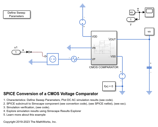
SPICE Conversion of a CMOS Voltage Comparator
This example shows a typical implementation of a CMOS voltage comparator and how you can convert a SPICE subcircuit to a Simscape™ component using the subcircuit2ssc function. You can use CMOS voltage comparators in analog to digital converter (ADC) or relaxation oscillator circuits.
In order to obtain the small-signal frequency response of the system, this example includes input u, output y, and includes a Solver Configuration block with the parameter Start simulation from steady state selected. You can use the linmod function to linearize this model.
Open the CMOS Voltage Comparator Subcircuit
In this example, you will convert this voltage comparator subcircuit to a Simscape component and analyze it in an existing model. The SPICE netlist named VoltageComparatorFromSPICE.cir is a netlist that describes the model of a CMOS voltage comparator.
* CMOS Voltage Comparator
* Simulation of Two-stage comparator

* Input Signals
VIN VP 0 AC 1V
VOS VN 0 DC 0V

* Power Supplies
VDD VDD 0 DC 5V
VSS VSS 0 DC -5V

* External Components
CL  VOUT  0        2pF

X1 VDD VSS VP VN VOUT COMPARATOR1
* Subcircuit for CMOS Voltage Comparator
.SUBCKT COMPARATOR1 VDD VSS VP VN VOUT
M1  N1  VN N2 VSS    NMOS1  W=680u   L=5u
M2  N3  VP N2 VSS    NMOS1  W=680u   L=5u
M3  N1  N1 VDD VDD    PMOS1  W=5u     L=5u
M4  N3  N1 VDD VDD    PMOS1  W=5u     L=5u
M5  N2  N4 VSS VSS    NMOS1  W=5u     L=5u
M6  VOUT  N3 VDD VDD    PMOS1  W=60u    L=5u
M7  VOUT  N4 VSS VSS    NMOS1  W=30u    L=5u
M8  N4  N4 VSS VSS    NMOS1  W=30u    L=5u
IS  0  N4      20u

.MODEL NMOS1 NMOS VTO=1 KP=17U
+ LEVEL=1
+ GAMMA=0.8 LAMBDA=0.015 PHI=0.6
+ LD=0.5U CJ=5E-4 CJSW=10E-10
+ U0=425 MJ=0.5 MJSW=0.5 CGSO=0.4E-9 CGDO=0.4E-9
.MODEL PMOS1 PMOS VTO=-1 KP=8U
+ LEVEL=1
+ GAMMA=0.4 LAMBDA=0.02 PHI=0.6
+ LD=0.8U CJ=5E-4 CJSW=10E-10
+ U0=200 MJ=0.5 MJSW=0.5 CGSO=0.4E-9 CGDO=0.4E-9
.ENDS

* Analysis
*.DC VIN  -1e-3 1e-3 1e-5
.AC DEC 10 1e-1 1e6
.PROBE
.END
Open the CMOS Comparator Subsystem
Open the VoltageComparatorFromSPICE model, which models the SPICE netlist by using SPICE blocks from the Simscape Electrical™ Additional Components library. This model includes a subsystem called CMOS Comparator. This subsystem is a manual implementation of the voltage comparator subcircuit, which you will replace with a Simscape component converted from the SPICE subcircuit.
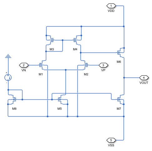
The subsystem describes the comparator in a schematic way. The plot below shows the outputs of the CMOS comparator circuit.
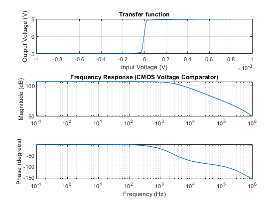
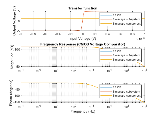
The gain is around 100 dB and the bandwidth is around 3 kHz. To define the minimum and maximum DC sweep input voltages and AC sweep frequencies, return to the top level of the model and double-click the block labeled Define Sweep Parameters. Click Plot DC AC simulation results in the model to run the simulation and plot the results.
However, for large SPICE netlists with multiple subcircuits, a manual conversion can be inefficient, time consuming, and error-prone. Simscape Electrical provides you with a way to automatically convert a SPICE netlist by using the subcircuit2ssc function.
Convert the SPICE Subcircuit to Simscape Component
You can convert SPICE components with either .cir or .lib extensions into Simscape components using the subcircuit2ssc function. The subcircuit2ssc function converts each .subckt section inside the SPICE netlist into a single component.
The validation files VoltageComparatorFromSPICETransferCharacteristic.mat and VoltageComparatorFromSPICEFrequencyResponse.mat are MATLAB® files that store data for the SPICE transfer characteristics and the small-signal frequency response.
Use the subcircuit2ssc function to convert the voltage comparator subcircuit, VoltageComparatorFromSPICE.cir, to a Simscape file and place it in a new directory called +myComparator.
Netlist converted. Review Simscape component files and make
manual edits for any unsupported items before building the
Simscape library located at:
+myComparator.
Generate the Simscape library using the ssc_build function.
Generating Simulink library 'myComparator_lib' in the current directory '/tmp/Bdoc25b_2988451_1047619/tpd999628c/simscapeelectrical-ex00700277' ...
Verify Simulation Results
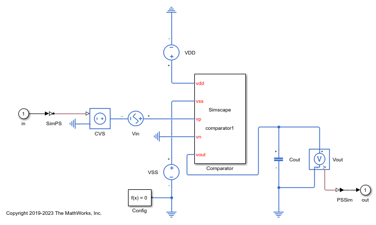
You must replace the CMOS Comparator subsystem with the converted component and rewire the terminals. To see the verification code, in the MATLAB Command Window, enter edit VoltageComparatorFromSPICEVerification. The script automatically connects the Simscape component generated from the conversion into the model. Then it obtains the transfer characteristics and the small-signal frequency response of the Simscape model by using a linearization method. The input voltage of the transfer characteristics is in the range of -1 V to 1 V, while the frequency range of the Bode plot is in the range of 0.1 Hz to 1 GHz. Finally, the script plots and compares the simulation results between a pure SPICE netlist model, the original model with the Simscape subsystem, and the model with the converted Simscape component obtained using subcircuit2ssc.
The plot below shows the simulation results from the three different models. The transfer characteristics and frequency response of the model with the converted Simscape component match those of the original SPICE netlist.
