RF Power Amplifier Characterization Test Harness
This example defines a test harness to estimate a non-linear behavioral model of a RF power amplifier from a Simscape™ Electrical™ simulation model.
Model Overview

This example comprises:
A semiconductor device model imported from a SPICE subcircuit
Three candidate power amplifier circuits
A quadrature amplitude modulation (QAM) input
Power Amplifier Specification
In this example, you can specify three different power amplifier circuits that you can compare when using the same transistor device: Class-A, Class-B with center-tapped transformer, and Class-B with a band-pass filter.
These are the specifications of the power amplifier:
Output power = 0.5W
DC voltage = 8V
Carrier frequency = 500-1500MHZ
Semiconductor Device Model
The semiconductor device in this example models an Infineon® bipolar transistor BFP196W. A SPICE netlist, downloaded from the manufacturer website, defines the behavior of this transistor. The subcircuit2ssc function is then used to convert the SPICE netlist into an equivalent Simscape language file.
To validate the parameterized SSC file, plot the I-V characteristics of the device by using the test harness in the RFPowerAmplifierIVTestHarness model. To plot the I-V characteristics, at the MATLAB Command Window, enter: RFPowerAmplifierIVTestHarnessPlot.
I-V Characteristics Test Harness
The circuit in this model estimates the transistor I-V characteristics.
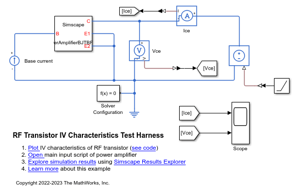
This figure shows the transistor I-V characteristics.

Select Power Amplifier Variant Subsystem
To enable easy switching between the three power amplifier circuits, this example uses a Simulink® variant subsystem. To select the desired variant, use the class workspace variable.

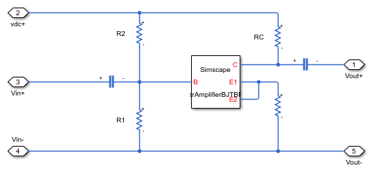
Class-A Power Amplifier
To use the class-A power amplifier, set the class workspace variable to 0.
Center Tapped Transformer
To use the class-B with center-tapped transformer power amplifier, set the class workspace variable to 1.

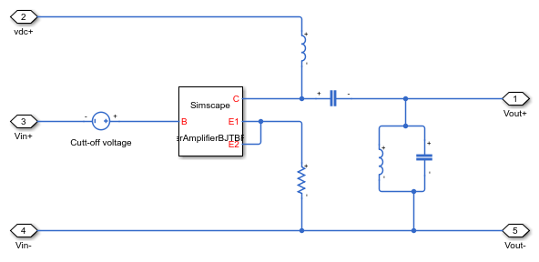
Bandpass Filter
To use the class-B with band-pass filter power amplifier, set the class workspace variable to 2.
Specify the Input Signal
In this example, you can choose between two input signals. The first option is a simple sinusoidal input in the carrier frequency. The second option is a quadrature amplitude modulation (QAM-16) input with the given band rate. Use the inputSignal workspace variable to choose between the two inputs.
inputSignal = 0, for sinusoidal input
inputSignal = 1, for QAM-16 input

Simulation Results with Sinusoidal Input
A sinusoidal input with 1GHz frequency is used to analyze the memoryless relation between the amplifier input and the output. Class-A Amplifier
This figure shows the simulation results with sinusoidal input for a Class-A amplifier.

This figure shows the simulation results with sinusoidal input for a Class-B amplifier with center-tapped transformer.
![]()
This figure shows the simulation results with sinusoidal input for a Class-B amplifier with band-pass filter.

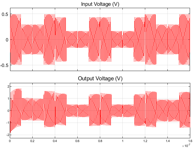
Simulation Results with QAM-16 Input
A QAM-16 input signal is used to study the memory effects of the RF power amplifier. This figure shows the simulation results with QAM-16 input for a Class-A amplifier.
This figure shows the simulation results with QAM-16 input for a Class-B amplifier with center-tapped transformer.
![]()