Modeling an Integrated Circuit
This example shows two ways to create a model of an integrated circuit that can be used in conjunction with other Simscape™ Electrical™ blocks. The first approach is to build a behavioral model using Simscape Foundation Library PS blocks and/or Simulink® blocks. The second is to build an implementation model from basic Simscape Electrical blocks. To look under the masks and view the details, select the relevant block and type ctrl-U.
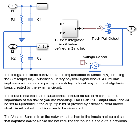
The behavioral model has the advantage of being simpler and potentially running faster. The approach can be extended to complex algorithms as might be implemented on a PIC or ASIC. Note that the model includes a first order lag to model the 1ns propagation delay. In many applications, this time constant will be much faster than the overall circuit dynamics, and may not be of interest. However, removing it potentially introduces an algebraic loop if the gate inputs depend in anyway on the gate output. An alternative is to implement the algorithm (the NOR gate in this case) using only PS blocks rather than Simulink blocks.
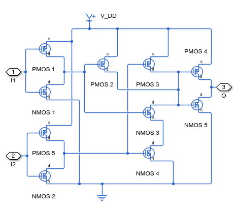
The implementation model implements a representation of the actual MOSFET gates used to implement the NOR function. Note that although it is a more representative model of the actual device, it still has limitations. A key challenge is selecting appropriate parameters for the MOSFET blocks based on the datasheet. Here all MOSFETS are assumed to have the same parameters which will not always be the case. The main disadvantage of using an implementation model is that simulation speed is likely to be much slower than the behavioral model.
Model

2-Input NOR (Behavioral Model) Subsystem
2-Input NOR (Implementation Model) Subsystem
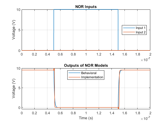
Simulation Results from Simscape Logging
The plots below show the inputs and outputs for the two implementations of the NOR circuit. The behavioral model and implementation model have nearly identical outputs.
See Also
Push-Pull Output | N-Channel MOSFET | P-Channel MOSFET