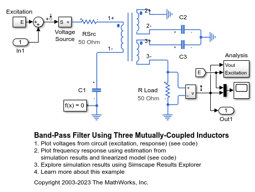
Band-Pass Filter Using Three Mutually-Coupled Inductors
This example shows an implementation of a band-pass filter using three mutually-coupled inductors. The model can be used to validate filter parameters which are chosen to provide a band-pass centered on 100MHz. A band-limited noise source is up-shifted by a 100MHz oscillator and applied to the filter. The response is then down-shifted by the oscillator. The model StopFcn callback takes FFTs of the source and response and estimates the filter frequency response.
Model
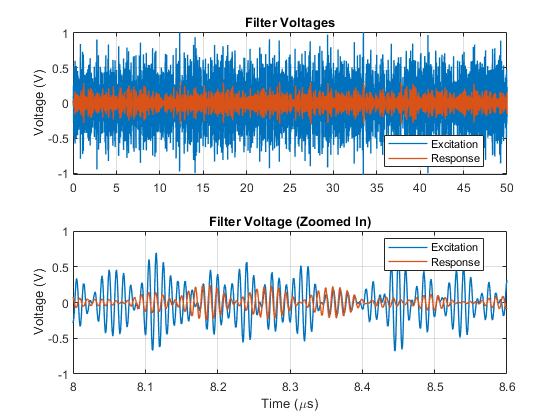
Simulation Results from Simscape Logging
The plot below shows the excitation voltage and the response of the bandpass filter circuit. A band-limited noise source is up-shifted by a 100MHz oscillator and applied to the filter. The response is then down-shifted by the oscillator.
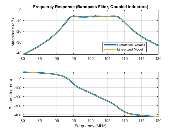
Frequency Response
The plot below shows the frequency response of the circuit obtained using two different methods. MATLAB® is used to apply an FFT to the simulation results to estimate the frequency response. The other method uses the MATLAB command linearize to obtain the frequency response. The two responses match nearly perfectly. The frequency response validates the filter design, showing that it is centered at 100 MHz.