Main Content

Voltage-Controlled Oscillator

Behavioral model of voltage-controlled oscillator

  • Voltage-Controlled Oscillator block

Libraries:
Simscape / Electrical / Integrated Circuits

Description

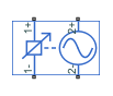
The Voltage-Controlled Oscillator block provides a behavioral model of a voltage-controlled oscillator (VCO). The output voltage is defined by the following equations:

vlim={vminfor vin<vminvinfor vminvinvmaxvmaxfor vin>vmax

Φ˙=2πF(vlim)

vout=Asin(2πfnomt+Φ)ioutRout

where:

  • vin is the voltage applied across the 1+ and 1– ports.

  • vout is the voltage across the 2+ and 2– ports.

  • fnom is the oscillator frequency when the input control voltage is vnom.

  • F is a linear function of vlim or a lookup table function of vlim.

  • A is the output voltage peak amplitude.

  • t is simulation time.

  • iout is the output current.

  • Rout is the output resistance.

If you choose Linear for the Frequency dependence on input voltage parameter, then the function F is given by:

F=fnom+k(vlimvnom)

where k is the rate of change of frequency with input voltage.

If you choose Tabulated for the Frequency dependence on input voltage parameter, then the function F is defined by the vectors of input voltages and corresponding output frequency deviations from nominal that you supply. The values for vmin and vmax are the first and the last values of the input voltage vector.

You can model the time delay between a change in the input control voltage and the oscillator frequency. Do this by modeling a first-order dynamic between vlim and the value passed to the function F.

Ports

Conserving

expand all

Electrical conserving port associated with the oscillator positive input voltage.

Electrical conserving port associated with the oscillator negative input voltage.

Electrical conserving port associated with the oscillator positive output voltage.

Electrical conserving port associated with the oscillator negative output voltage.

Parameters

expand all

Frequency

Select one of the following methods for block parameterization:

  • Linear — Define a linear function by specifying the rate of change of frequency with input voltage. This is the default option.

  • Tabulated — Provide the vectors of input voltages and corresponding output frequency deviations from nominal. The block determines the frequency deviation by table lookup based on these values.

The oscillator frequency when the input control voltage is at the nominal value.

The input voltage corresponding to the oscillator nominal frequency.

Dependencies

This parameter is visible only when you select Linear for the Frequency dependence on input voltage parameter.

The linear coefficient defining the rate of change of frequency depending on input voltage.

Dependencies

This parameter is visible only when you select Linear for the Frequency dependence on input voltage parameter.

The minimum input voltage that affects VCO frequency.

Dependencies

This parameter is visible only when you select Linear for the Frequency dependence on input voltage parameter.

The maximum input voltage that affects VCO frequency.

Dependencies

This parameter is visible only when you select Linear for the Frequency dependence on input voltage parameter.

The vector of voltages for the tabulated VCO frequency.

Dependencies

This parameter is visible only when you select Tabulated for the Frequency dependence on input voltage parameter.

The corresponding vector of VCO frequencies relative to the nominal frequency.

Dependencies

This parameter is visible only when you select Tabulated for the Frequency dependence on input voltage parameter.

Electrical Characteristics

The peak amplitude of the voltage across the 2+ and 2– terminals.

The resistance seen at the 1+ and 1– terminals.

The value of the series output resistance.

Dynamics

Select one of the following methods for specifying dynamics:

  • No dynamics — Do not model the time delay between a change in the input control voltage and the oscillator frequency. This is the default option.

  • Model frequency tracking dynamics — Model a first order dynamic between the input control voltage and the oscillator frequency.

Time constant for the first-order filter that delays the measured input control voltage, to model the lag between a change in VCO demanded frequency and the resulting VCO frequency.

Dependencies

This parameter is visible only when you select Model frequency tracking dynamics for the Dynamics parameter.

The initial VCO output frequency.

Extended Capabilities

C/C++ Code Generation
Generate C and C++ code using Simulink® Coder™.

Version History

Introduced in R2013b