Two-Pulse Gate Multiplexer
Multiplex gate input signals to two quadrant chopper

Libraries:
Simscape /
Electrical /
Semiconductors & Converters /
Converters
Description
The Two-Pulse Gate Multiplexer block multiplexes two separate voltage signals into a single vector. The vectorized signal can control the gates of two switching devices in a converter, such as a Two-Quadrant Chopper block.
Model
This block can model a two-pulse gate multiplexer through either physical signal ports or electrical ports:
PS ports — Two-pulse gate multiplexer with physical signal ports. Set the Gate-control port parameter to
PSto control switching device gates in a converter block using Simulink® gate-control voltage signals. To multiplex and connect Simulink signals to the gate-control inport of a converter block:Convert each voltage signal using a Simulink-PS Converter block.
Multiplex the converted gate signals into a single vector using the multiplexer block.
Connect the vector signal to the G port of the converter.
Electrical ports — Two-pulse gate multiplexer with electrical conserving ports. To control switching device gates in a converter block using Simscape™ Electrical™ Electronics and Mechatronics blocks, set the Gate-control port parameter to
Electrical. The electrical ports include pairs of electrical connections. Each pair corresponds to the gate and cathode of a switching device in the connected converter block.
Examples

First and Second Quadrant Chopper Control
Control a two-quadrant chopper. The two-quadrant chopper operates in the first and second quadrants, allowing positive and negative output current. The Control subsystem implements a simple PI-based control algorithm for controlling the output current. The load of the system is considered constant throughout the simulation.

BLDC Speed Control
Control the rotor speed in a BLDC based electrical drive. An ideal torque source provides the load. The Control subsystem uses a PI-based cascade control structure with an outer speed control loop and an inner dc-link voltage control loop. The dc-link voltage is adjusted through a DC-DC buck converter. The BLDC is fed by a controlled three-phase inverter. The gate signals for the inverter are obtained from hall signals. The simulation uses speed steps. The Scopes subsystem contains scopes that allow you to see the simulation results.
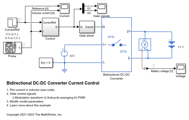
Bidirectional DC-DC Converter Current Control
Control the inductor current of a Bidirectional DC-DC Converter. To adjust the duty cycle, the Control subsystem uses a PI-based control algorithm. The Bidirectional DC-DC Converter uses averaged switches. To achieve different levels of fidelity, you can use either modulation waveforms, averaged gate pulses, or gate pulses.

Two-Phase DC-DC Converter Current Control
Control the current of a two-phase interleaved bidirectional DC-DC converter. The two-phase converter comprises two Bidirectional DC-DC Converter with ideal IGBTs. To adjust the duty cycle, the Control subsystem uses a PI-based control algorithm. To reduce the ripple at the output port of the converter, the two phases are switched with the same duty ratio but with a relative phase shift of 180 degrees. The Scopes subsystem contains scopes that allow you to see the simulation results.