SPDT Switch
Single-pole double-throw switch

Libraries:
Simscape /
Electrical /
Switches & Breakers
Description
The SPDT Switch block models a single-pole double-throw switch:
When the switch is open, port p is connected to port n1.
When the switch is closed, port p is connected to port n2.

Open connections are modeled by a resistor with value equal to the reciprocal of the Open conductance parameter value. Closed connections are modeled by a resistor with value equal to the Closed resistance parameter value.
If the Threshold width parameter is set to zero, the switch is closed if the voltage presented at the vT control port exceeds the value of the Threshold parameter.
If the Threshold width parameter is greater than zero, then switch conductance G varies smoothly between off-state and on-state values:
The block uses the function 3λ2 – 2λ3 because its derivative is zero for λ = 0 and λ = 1.
Defining a small positive Threshold width can help solver convergence in some models, particularly if the control port signal vT varies continuously as a function of other network variables. However, defining a nonzero threshold width precludes the solver making use of switched linear optimizations. Therefore, if the rest of your network is switched linear, set Threshold width to zero.
Optionally, you can add a delay between the point at which the voltage at
vT passes the threshold and the switch opening
or closing. To enable the delay, on the Dynamics tab,
set the Model dynamics parameter to Model
turn-on and turn-off times.
Model Gate Control Port
You can control the switch gates by using a physical signal port or electrical conserving ports. To select the gate control port, set the Modeling option parameter to either:
PS control port— The block contains a physical signal port that is associated with the threshold voltage.Electrical control port— The block contains electrical conserving ports that are associated with the threshold voltage.
Examples
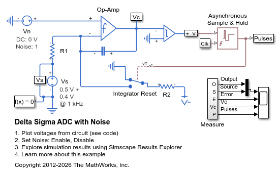
Delta Sigma ADC with Noise
A simple implementation of a sigma delta analog-to-digital converter. An input in the range 0 to Vref (=1V) is integrated until it causes the integrator to reset. The time to reset is proportional to the input value. Demodulation of the pulses is performed by a low-pass filter. The Asynchronous Sample & Hold block behaves like an edge-triggered D-type flip-flop, passing input U to output Y only on a rising edge of the clock. This model can be used to explore and understand the effect of op-amp impairments such as equivalent input noise on converter accuracy. To turn off the noise, open block Vn and select 'Disabled' for the noise mode.
Ports
Refer to the figure for port locations.

Input
Conserving
Parameters
Extended Capabilities
Version History
Introduced in R2012b