Main Content

Governor Type 1

IEEE type 1 linearized speed-governing steam turbine model

Since R2020a

  • Governor Type 1 block

Libraries:
Simscape / Electrical / Control / Turbine-Governors

Description

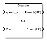
The Governor Type 1 block models a model IEEEG1 steam turbine-governor model IEEEG1.

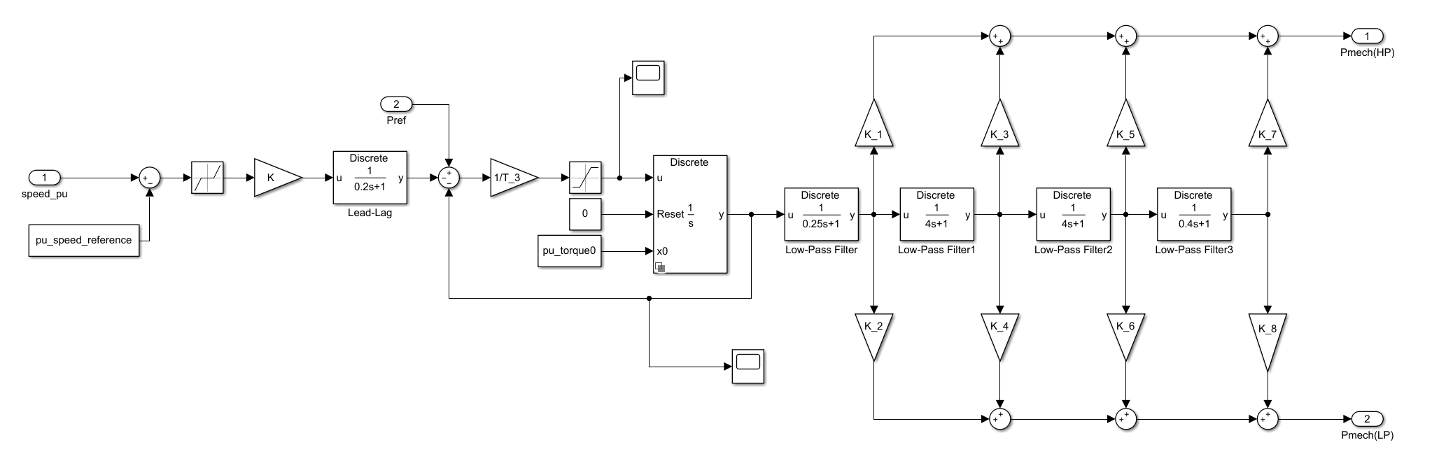
This block allows the modeling of cross-compound units and it has two sets of turbine fractions:

  • LP Fraction, K_2, LP Fraction, K_4, LP Fraction, K_6, LP Fraction, K_8 for low-pressure (LP).

  • HP Fraction, K_1, HP Fraction, K_3, HP Fraction, K_5, HP Fraction, K_7 for high-pressure (HP).

You can switch between continuous and discrete implementations of the block by using the Sample time (-1 for inherited) parameter. To configure the governor for continuous time, set the Sample time (-1 for inherited) property to 0. To configure the governor for discrete time, set the Sample time (-1 for inherited) property to a positive, nonzero value, or to -1 to inherit the sample time from an upstream block.

This diagram illustrates the overall structure of the block:

Ports

Input

expand all

Speed of the turbine, in per-unit representation, specified as a scalar.

Data Types: single | double

Bias to the speed load reference, specified as a scalar. Connect this port to the Pref output port of a turbine load controller block, such as the Controller LCFB1 block.

Data Types: single | double

Output

expand all

High-pressure mechanical power, returned as a scalar.

Data Types: single | double

Low-pressure mechanical power, returned as a scalar.

Data Types: single | double

Parameters

expand all

General

Per-unit speed reference.

Per-unit initial torque at the start of the simulation.

Time between consecutive block executions. During execution, the block produces outputs and, if appropriate, updates its internal state. For more information, see What Is Sample Time? and Specify Sample Time.

For inherited discrete-time operation, set this parameter to -1. For discrete-time operation, set this parameter to a positive integer. For continuous-time operation, set this parameter to 0.

If this block is in a masked subsystem or a variant subsystem that supports switching between continuous operation and discrete operation, promote this parameter to ensure correct switching between the continuous and discrete implementations of the block. For more information, see Promote Block Parameters on a Mask.

Governor

Per-unit gain of the governor.

Equivalent lag time constant. This parameter is associated with the block labeled "Lead-Lag" in the diagram. Set this parameter to 0 when the additional lag dynamics are negligible.

Equivalent lead time constant. This parameter is associated with the block labeled "Lead-Lag" in the diagram. Set this parameter to 0 when the additional lead dynamics are negligible.

Time constant of the valve position, in seconds.

Per-unit maximum opening rate of the valve.

Per-unit maximum closing rate of the valve.

Per-unit maximum opening of the valve, on MW capability.

Per-unit minimum opening of the valve, on MW capability.

Time constant of the inlet steam bowl, in seconds. This parameter is associated with the block labeled "Low-Pass Filter" in the diagram.

Fraction of the high-pressure shaft power after the first boiler pass.

Fraction of the low-pressure shaft power after the first boiler pass.

Time constant of the second boiler pass, in seconds. This parameter is associated with the block labeled "Low-Pass Filter1" in the diagram.

Fraction of the high-pressure shaft power after the second boiler pass.

Fraction of the low-pressure shaft power after the second boiler pass.

Time constant of the third boiler pass, in seconds. This parameter is associated with the block labeled "Low-Pass Filter2" in the diagram.

Fraction of the high-pressure shaft power after the third boiler pass.

Fraction of the low-pressure shaft power after the third boiler pass.

Time constant of the fourth boiler pass, in seconds. This parameter is associated with the block labeled "Low-Pass Filter3" in the diagram.

Fraction of the high-pressure shaft power after the fourth boiler pass.

Fraction of the low-pressure shaft power after the fourth boiler pass.

Intentional deadband width.

References

[1] Dynamic Models for Steam and Hydro Turbines in Power System Studies, IEEE Transactions on Power Apparatus and Systems. Vol. PAS-92, Number 6, 1973, pp. 1904–1915.

[2] Task Force on Turbine-Governor Modeling, Dynamic models for turbine-governors in power system studies, IEEE Power Energy Society, January 2013.

[3] IEEE Guide for the Application of Turbine Governor Systems for Hydroelectric Generating Units, IEEE Std 1207-2011.

Extended Capabilities

C/C++ Code Generation
Generate C and C++ code using Simulink® Coder™.

Version History

Introduced in R2020a