Main Content

AC-DC Converter (Three-Phase)

Behavioral model of AC-DC converter

Since R2022b

Libraries:
Simscape / Electrical / Semiconductors & Converters / Converters

Description

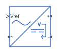
This block represents the behavioral model of an AC-DC converter. Use this block to model AC-DC converters without simulating individual switching events. Use the DC voltage reference input to convert the electrical energy between the AC and DC sides.

This block is compatible with time simulation mode and frequency-and-time simulation mode.

Equations

DC Side

At the DC side, if you set the Voltage dynamics at DC side parameter to No dynamics, the block calculates the output voltage, VDC, by using this equation:

VDC=VrefDIDC,

where Vref is the value of the input signal at the Vref port, D is the value of the Output DC voltage droop with output current parameter, and IDC is the output DC current.

If you set the Voltage dynamics at DC side parameter to Specify voltage regulation time constant, the block calculates the output voltage, VDC, by using this equation:

τDCV˙DC+VDC=VrefDIDC,

where τDC is the value of the Voltage regulation time constant at DC side parameter.

The power at the DC side is

PDC=VDCIDC.

AC Side

If you set the Power balance dynamics parameter to No dynamics, the input power at the AC side is equal to the output power at the DC side.

PAC=PDC.

If you set the Power balance dynamics parameter to Specify power time constant, the block calculates the input power at the AC side by using this equation:

τPP˙AC+PAC=PDC,

where τP is the value of the Power balance time constant parameter.

To determine the three-phase input currents at the AC side, the block first calculates the dq-axes voltages, vd and vq, using the Park transform on the abc-phase voltages, va, vb, and vc:

[vdvq]=23[sinθsin(θ120°)sin(θ+120°)cosθcos(θ120°)cos(θ+120°)][vavbvc]

where θ=2πFratedt is the angle of the synchronously rotating reference frame.

The block then calculates the three-phase AC currents, ia, ib, and ic, by using these power equations:

PAC=32(vdid+vqiq)QAC=0=32(vdidvqiq).

From these equations, the dq-axes currents, id and iq, are

id=23PACvdxvdx2+vqx2iq=23PACvqxvdx2+vqx2,

where vdx and vqx are obtained from these equations:

τACv˙dx+vdx=vdτACv˙qx+vqx=vq,

where τAC is the value of the Voltage time constant at AC side parameter.

Finally, the block calculates the three-phase AC currents that flow into the converter by using this equation:

[iaibic]=[sinθcosθsin(θ120°)cos(θ120°)sin(θ+120°)cos(θ+120°)][idiq].

Limitations

The AC-DC Converter (Three-Phase) block does not model the power losses.

Ports

Input

expand all

Physical signal input port associated with the external signal of the DC voltage reference.

Conserving

expand all

Expandable three-phase port.

Dependencies

To enable this port, set Electrical connection to Composite three-phase ports.

Electrical conserving port associated with the a-phase.

Dependencies

To enable this port, set Electrical connection to Expanded three-phase ports.

Electrical conserving port associated with the b-phase.

Dependencies

To enable this port, set Electrical connection to Expanded three-phase ports.

Electrical conserving port associated with the c-phase.

Dependencies

To enable this port, set Electrical connection to Expanded three-phase ports.

Electrical conserving port associated with the positive terminal.

Electrical conserving port associated with the negative terminal.

Parameters

expand all

Option to model composite or expanded three-phase ports.

Amount of voltage that the output DC voltage drops from the set point for an output current of 1 A.

Option to include voltage regulation dynamics. If you set this parameter to No dynamics, the block does not consider the voltage regulation dynamics. If you set this parameter to Specify voltage regulation time constant, the block adds a first-order lag to the equation that defines the value of the DC voltage source.

Time constant associated with the voltage transients at the DC side when the load current at the DC side is stepped.

Dependencies

To enable this parameter, set Voltage dynamics at DC side to Specify voltage regulation time constant.

DC side output voltage at time zero. To initialize the model with no transients when it delivers a steady-state load current, use this parameter to set the initial DC side output voltage.

Dependencies

To enable this parameter, set Voltage dynamics at DC side to Specify voltage regulation time constant.

Rated electrical frequency at AC side.

Minimum value of the phase-to-phase RMS AC-side voltage for the converter to produce a DC output voltage.

Time constant associated with the voltage measurement transients at the AC side.

Phase-to-phase RMS voltage at the AC-side at time zero. The value of this parameter must be greater than the value of the Minimum AC side voltage (phase-to-phase RMS) parameter.

Initial voltage angle of the a-phase at time zero for the AC side.

Whether to include power balance dynamics. If you set this parameter to No dynamics, the block does not consider power balance dynamics. If you set this parameter to Specify power time constant, the block adds a first-order lag to the equation that defines the AC-side power. When you enable the dynamics, a DC-side output power change results in a transient change in the input power at the AC side.

Time constant associated with the transients of the power balance between the AC and DC side.

Dependencies

To enable this parameter, set Power balance dynamics to Specify power time constant.

Initial active power at time zero at the AC side.

Dependencies

To enable this parameter, set Power balance dynamics to Specify power time constant.

Parasitic conductance to the electrical reference.

Extended Capabilities

C/C++ Code Generation
Generate C and C++ code using Simulink® Coder™.

Version History

Introduced in R2022b