Main Content

SENT Configuration

Map data transfer over SENT protocol in the Infineon AURIX model to peripheral registers in the MCU

Since R2023b

Description

View and edit the map of SENT protocol used in the Infineon® AURIX™ model to the hardware peripherals.

Using the Peripheral Configuration tool, you can:

  • View and edit configuration parameters for SENT block.

  • Check for conflicts, if any between peripherals.

SENT peripheral

Open the SENT Configuration

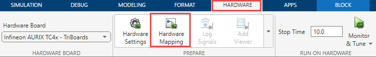
  • In the Hardware tab, click Hardware Mapping.

    Hardware Mapping

Parameters

expand all

Basic > SENT pin configuration

Select the module (0 or 1) through which data transfer should take place over SENT protocol.

Select the pin number for reading the data over SENT protocol.

Dependencies

The available pins depend on your selection for the Module parameter.

Select the state of communication line used for SENT protocol.

Select the state of communication line used for SPC mode.

Speed of data transmission over SENT protocol.

Voltage level of the pin based on the application of SENT protocol.

Basic > SENT protocol properties

Tick time to convert the data received over SENT protocol.

Number of nibbles per frame.

Signal level of SENT protocol.

Advanced > Standard frame

CRC check for the standard frame received over SENT protocol.

Option to include Status nibble in CRC check.

Advanced > Slow serial data

Slow serial data processing over SENT channel.

Dependencies

This parameter appears only if you select the Serial parameter in the SENT block in the Simulink® model.

Specify serial frame structure over SENT channel.

Dependencies

This parameter appears if you enable the Serial data processing parameter.

CRC check for serial data received over SENT protocol.

Dependencies

This parameter appears if you enable the Serial data processing parameter.

Advanced > SPC protocol

Select the source of trigger for SPC transmission.

Dependencies

This parameter appears only if you select the SENT Protocol parameter as SPC.

Select the source of hardware trigger for SPC transmission.

The Sent trigger signal depends on the choice of Source of hardware trigger parameter. The available sent trigger signals for different combinations of timer module, timer submodule and timer unit are:

ModuleTimer unit Sent trigger signal
eGTMTOM0/ATOM0Sent_TriggerSignal_0
TOM1/ATOM1Sent_TriggerSignal_1
ATOM2Sent_TriggerSignal_2
GTMTOM0/ATOM0Sent_TriggerSignal_3
TOM1/ATOM1Sent_TriggerSignal_4
TOM2/ATOM2Sent_TriggerSignal_5
TOM3/ATOM3Sent_TriggerSignal_6
TOM4/ATOM4Sent_TriggerSignal_7
TOM5/ATOM5Sent_TriggerSignal_8
ATOM6Sent_TriggerSignal_9
ATOM7Sent_TriggerSignal_10
ATOM8Sent_TriggerSignal_11
ATOM9Sent_TriggerSignal_12
ATOM10Sent_TriggerSignal_13
ATOM11Sent_TriggerSignal_14

Dependencies

This parameter appears only if you select the Trigger source parameter as Hardware trigger.

Specify sensor count for sensor selection.

This parameter decides the number of SPC pulses to configure in the sensor selection mode.

Dependencies

This parameter appears only if you select the SPC Mode parameter as Sensor selection.

Specify pulse length for SPC pulse #.

Note

  • You can configure up to 3 SPC pulses if you set the SPC Mode parameter as Feature selection.

  • You can configure up to 4 SPC pulses (based on Sensor count parameter) if you set the SPC Mode parameter as Sensor selection.

Dependencies

This parameter appears only if you select the SENT Protocol parameter as SPC.

Specify pulse delay for SPC pulse #.

Note

  • You can configure up to 3 SPC pulses if you set the SPC Mode parameter as Feature selection.

  • You can configure up to 4 SPC pulses (based on Sensor count parameter) if you set the SPC Mode parameter as Sensor selection.

Dependencies

This parameter appears only if you select the SENT Protocol parameter as SPC.

Advanced > Events

Option to add interrupt for standard data reception.

Option to add interrupt for serial data reception.

Option to add interrupt for communication error (for example, CRC check).

Enabling communication error can trigger interrupt in any of the following cases:

  • Received synchronization / calibration pulse has deviated by permissible limit from nominal value.

  • Received synchronization / calibration pulse has deviated by permissible limit from predecessor value.

  • Wrong number of nibbles are received.

  • Nibble value received is outside range of 0 to 15.

  • Status and communication nibble is wrong, that is, start bit is 1 in frame other than n-by-16.

  • CRC check for serial data has failed.

Option to add interrupt for receive buffer overflow error.

Option to add interrupt for transmit buffer underflow error.

Option to add interrupt for watchdog error.

Service request line for the interrupts (based on the above parameters, if selected).

Note

All interrupts for a selected SENT module are serviced using a single service request line.

Dependencies

Service request line is enabled only if at least one of the above mentioned interrupt events are enabled.

Advanced > Miscellaneous

Option to add digital filter depth.

Option to enable frequency drift for data transmission over SENT protocol.

Option to ignore pause pulse for data transmission over SENT protocol.

Advanced > Nibble order

Eight groups of receive data bits - Receive data bits[0:3] to Receive data bits[28:31]. Select the nibble number for each of the eight groups to form the 32-bit data output.

Version History

Introduced in R2023b

See Also