Package Delivery Quadcopter
This example models a package delivery quadcopter. The quadcopter takes off from the launchpad and delivers the package to the drop-off location while following a desired trajectory.
Model
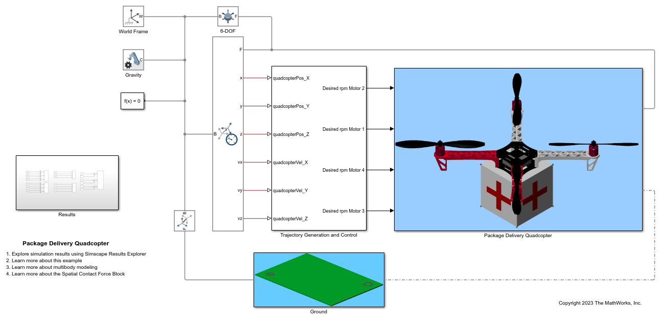
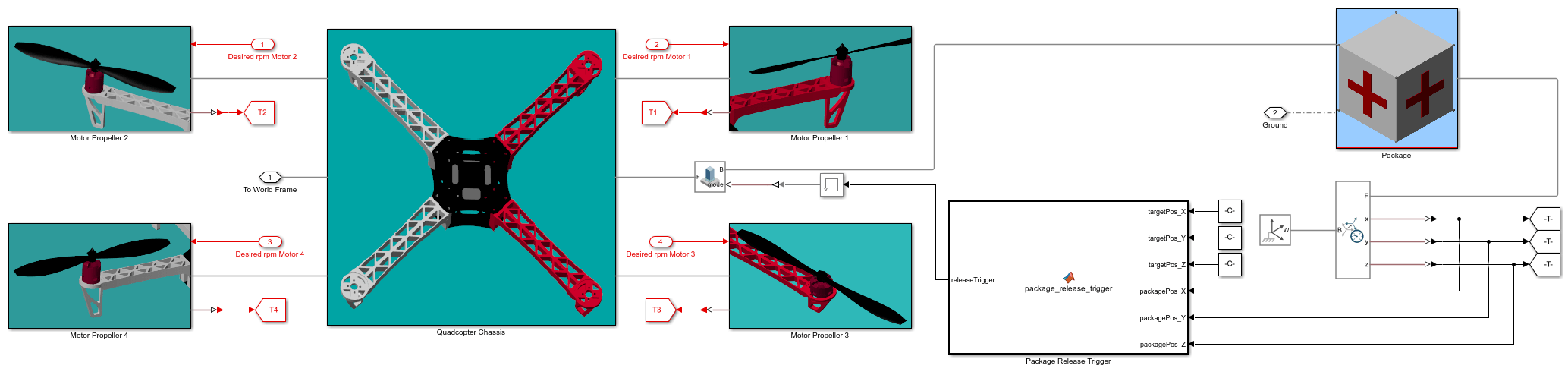
Package Delivery Quadcopter Subsystem
The quadcopter comprises of a chassis and four motor-propeller pairs, each spinning alternately in clockwise and counterclockwise direction. The quadcopter chassis has four identical arms rigidly attached to the top and bottom plates using the Rigid Transform block. The motor comprises of a motor base, a motor shaft which is connected to the motor base via revolute joint and a motor cap. The propeller is rigidly attached to the motor shaft. The motor base is rigidly connected to the arm using the Rigid Transform Block. Based on the rotational speed of the propeller, the thrust coefficient and thrust generated by each propeller are calculated. The package is attached to the quadcopter via weld joint. Whenever the quadcopter carrying the package gets in the proximity of the drop-off location, the MATLAB Function block: Package Delivery Quadcopter/Package Release Trigger disengages the weld joint to deliver the package. The Spatial Contact Force blocks are used to model the contact forces between the package and the ground surface.
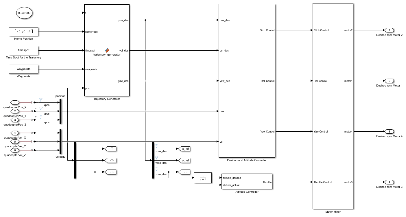
Trajectory Generation and Control Subsystem
The desired trajectory of the quadcopter is computed using the MATLAB Function block: Trajectory Generation and Control/Trajectory Generator. The waypoints between the launchpad and the drop-off location are prescribed. Given the current time, the block returns a 5th order polynomial trajectory (desired position and velocity) for the quadcopter. The trajectory between two successive waypoints is computed as a piecewise 5th order polynomial such that the initial and final velocities and accelerations at the waypoints are all zero. Whenever the quadcopter gets in the proximity of a waypoint, the desired trajectory is computed between the current and the next waypoint. The quadcopter hovers when it reaches the drop-off location and delivers the package. The Trajectory Generation and Control/Position and Attitude Controller and Trajectory Generation and Control/Altitude Controller subsystems generate the control signals that drives the actual attitude and altitude of the quadcopter to the desired values. The Trajectory Generation and Control/Motor Mixer subsystem uses the attitude and the altitude control signals to compute the desired rotational speed for the quadcopter motors.
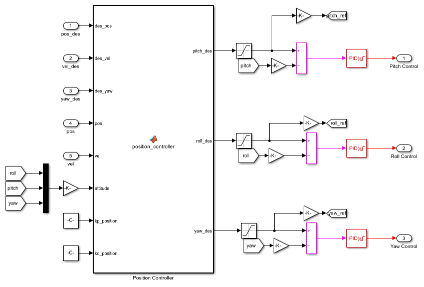
Position and Attitude Control Subsystem
A cascade control is used to drive the position of the quadcopter to the desired state. The inner loop contains a PID controller which controls the attitude dynamics of the quadcopter. A backstepping controller inside MATLAB Function block: Position and Attitude Controller/Position Controller computes the desired roll and pitch angles necessary to achieve the control objective.
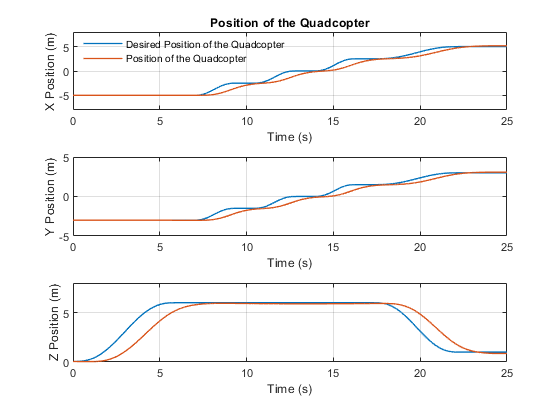
Simulation Results from Simscape Logging
The plot below shows the actual and desired position of the Quadcopter
References : [1] Das, A., Lewis, F. and Subbarao, K., 2009. Backstepping approach for controlling a quadrotor using lagrange form dynamics. Journal of Intelligent and Robotic Systems, 56(1), pp.127-151.