Specify Input Ranges on Simulink and Stateflow Elements
When you specify input range constraints on Simulink® and Stateflow® elements, Simulink Design Verifier™ considers these constraints during analysis.
Specify Input Ranges for Inport Blocks
After you specify the output minimum and maximum values on Inport blocks, Simulink Design Verifier analysis uses the minimum and maximum values as constraints.
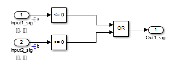
The following example model restricts the signals from two Inport blocks:
Input1 block: Minimum: 1, Maximum: 5
Input2 block: Minimum: -1, Maximum: 1

When you use Simulink Design Verifier, to analyze this model, the analysis produces these results:
The output from Input1 is never less than 0, therefore the first input to the Logical Operator block is never
false. The objective that the first input to the Logical Operator equalsfalseis unsatisfiable.The Logical Operator block cannot achieve 100% modified condition/decision coverage (MCDC) coverage because the condition where the first input is
falsenever occurs.
The detailed analysis report shows the values you use as constraints for Input1 and Input2.
Note
Simulink Design Verifier consider values of minimum and maximum constraints for root-level inports only.
Specify Input Ranges for Simulink.Signal Objects
Using the Model Explorer, in the model workspace, you can
specify minimum and maximum values on Simulink.Signal
objects associated with input signals.
The following example model uses the Simulink.Signal objects
associated with the input signals a and b to
restrict the signal values:
Signal
a: Minimum: 1, Maximum: 5Signal
b: Minimum: -1, Maximum: 1
When you analyze this model, the results are the same as if you specified the minimum and maximum values on the input ports.
Specifying Signal Ranges on Inport Blocks and Signals
If you specify ranges on the Inport blocks and on the signals, the analysis
considers the smallest range for the values. For example, if you specify a range
of 4..12 on an input port and a range of
1..8 on the signal from the input port, the analysis
considers the range 4..8.
Specify Input Ranges for Stateflow Data Objects
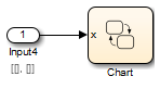
Using the Model Explorer, you can specify ranges on data objects that are directly connected to the root-level input ports for a Stateflow chart.
In the following example model, the Stateflow chart named Chart has a data object, x, whose range
you specified as 0 < x < 10. In this chart,
x must be greater than 15 to trigger the transition from
low to high.
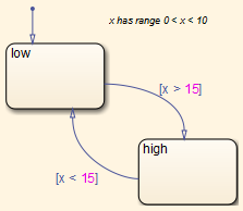
The value of x ranges from 0 through 10, therefore the
transition condition [x > 15] is never
true. The transition from low to
high never occurs.
Because the high state is
never entered, the transition condition
[x < 15] is never
tested, and the transition from high to low
never occurs. The chart is
always in the low
state.
When you analyze this model, these objectives are proven unsatisfiable:
The
highstate is never entered.The transition condition
[x > 15]is alwaysfalse, nevertrue.The condition
[x < 15]is never tested, so it is nevertrueorfalse.
The analysis report indicates the values that you use as constraints for
x: [0, 10].
Specify Input Ranges for Subsystems
The Simulink Design Verifier software considers specified input minimum and maximum values as constraints only at the top level of a model. You can specify minimum and maximum values on Input ports on subsystems, but when you analyze the top-level model, the software ignores those values.
When you perform the subsystem analysis, the software considers specified minimum and maximum values on the input ports of the subsystem.
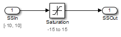
For example, consider the following model and its subsystem.
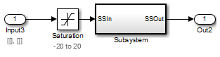
In Subsystem, the specified minimum and maximum values for input port SSIn are -10 and 10, respectively. The lower and upper limits for the Saturation block are -15 and 15, respectively.
The analysis considers the specified minimum and maximum values as constraints on
the SSIn port if you right-click the subsystem and click the
Generate Tests button ![]() from the Design Verifier app section to generate
tests.
from the Design Verifier app section to generate
tests.
Constraints: Design Min Max Constraints
The analysis identifies two unsatisfiable objectives:
input > lower limit F: The input is always greater than the lower limit on the Saturation block (-15).
input >= upper limit T: The input is never greater than or equal to the upper limit on the Saturation block (15).
If you analyze the model that contains Subsystem, the analysis does not consider
the values specified on the input port SSIn in the subsystem. The
analysis considers only the root-level input ports at the respective level of the
hierarchy for analysis.
Specify Input Ranges for Global Data Stores
A data store is a repository to which you can write data
and from which you can read data, without having to connect an input or output
signal directly to the data store. You create a data store by using a Data Store Memory block or a
Simulink.Signal object. You can
specify
minimum and maximum values for any
data store.
During subsystem analysis, Simulink Design Verifier creates an input port to mimic the execution context for a global data store. For more information, see Extract Subsystems for Analysis. If the data store has specified minimum and maximum values, those values are assigned as minimum and maximum values on the new input port. Simulink Design Verifier analysis considers the input minimum and maximum values as subsystem-level analysis constraints.
In the following example model, data store A has a minimum
value of 0 and a maximum value of 10.
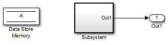
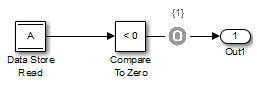
The atomic subsystem reads values from the data store and checks to see if the
input is less than 0. The Compare To Zero block
outputs 1 if the input is less than 0, and outputs 0 if the input is greater than or
equal to 0. The Test Objective block checks to see if the output is
ever 1.
If you right-click the subsystem in the top-level model and select the Generate
Tests button ![]() from the Design Verifier app section to generate
tests, the analysis considers the constraints for data store
from the Design Verifier app section to generate
tests, the analysis considers the constraints for data store A to
be [0, 10].
The analysis does not satisfy the objective specified in the Test Objective block. The input is always greater than or equal to 0, therefore the output from the Compare To Zero block is always 0.
Specify Input Ranges for Bus Elements
When you define a bus, you can Work with Signal Ranges in Blocks. Simulink® Design Verifier™ considers these minimum and maximum values when analyzing subsystems and models that use the bus as an input signal.
Consider a subsystem that inputs a bus of three fields, each with a defined minimum and maximum. Open the model sldvBusMinMaxExample to view the subsystem.
open_system('sldvBusMinMaxExample');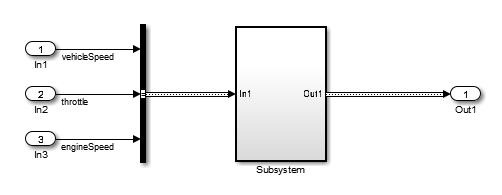
Bus Element | Bus Element Minimum | Bus Element Maximum |
|---|---|---|
vehicleSpeed | 0 | 125 |
throttle | 0 | 100 |
engineSpeed | 0 | 7600 |
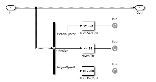
The subsystem has test objectives that confirm that each element does not exceed a constant. The vehicleSpeed signal is limited to a maximum value lower than the test objective.
In the top-level mode, right-click the subsystem. To add the Design Verifier app options to the menu, point to Select Apps and click the Design Verifier button ![]() . Then, in the Design Verifier app section, click the Generate Tests button
. Then, in the Design Verifier app section, click the Generate Tests button ![]() to generate the tests for the Subsystem. The Condition Objective for testing
to generate the tests for the Subsystem. The Condition Objective for testing vehicleSpeed > 135 is not satisfiable due to the maximum specification on the vehicleSpeed element.
Using Specified Input Minimum and Maximum Values as Constraints
This example shows how to use input port minimum and maximum values as analysis constraints by Simulink® Design Verifier™ during both test generation and property proving.
This model is preconfigured to generate tests for MCDC. The specified minimum and maximum values are displayed in square brackets. The constraints in this example prevent some of the coverage objectives from being satisfied. When you generate tests without considering these constraints, all of the coverage objectives are satisfied.
1. The Input1 and Input2 minimum and maximum values are captured directly on their respective inport signal attributes.
2. The minimum and maximum values are specified on the Simulink.Signal objects associated with signals a and b. Simulink Design Verifier uses the signal object's values as constraints. When multiple minimum and maximum values are specified, e.g., on the inport and on the signal object, Simulink Design Verifier considers their tightest range.
3. Simulink Design Verifier considers the minimum and maximum limit ranges specified on Stateflow® data that is directly connected to the root-level input ports.
4. For subsystem analysis, the subsystem root-level specified input minimum and maximum values are considered. Observe that generating tests for the Subsystem uses the constraints specified on SSIn, but ignores them for the system-level analysis.
open_system('sldvdemo_minmaxconstraints');
