Design Optimization Tuning Parameters in Referenced Models (GUI)
This example shows how to tune parameters in referenced models using the Response Optimizer app.
Motor Control Model
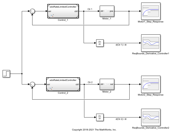
The model shows the control of angular position for two motors. Open the Simulink® model.
open_system('sdoMultipleMotors')
Model references are used for the two controllers, which are instances of the same model. Open the controller.
open_system('sdoRateLimitedController')
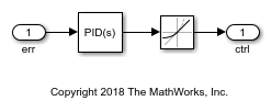
Each controller has PID gains Kp, Ki, and Kd, and a slew rate, Slew. The Slew value limits the rate at which the control signal changes, so that currents drawn from the power supply stay within the power supply's limits. The Slew value is common to both instances of the controller. In contrast, the PID gains need to be different for each instance of the controller, since the motors being controlled have different characteristics. Therefore, the PID gains are specified as model arguments in the controller's model workspace. The PID gain values are set at the level of the sdoMultipleMotors model.
Design Problem
The control reference signal is a step change in position, which occurs at 1 second. Each motor's angular position should follow the reference signal, but the first motor has a smaller moment of inertia and can respond more quickly to changes in the reference signal. The angular position of the first motor must satisfy the following requirements:
Rise time: 2 seconds
Settling time: 7 seconds
The second motor has a larger moment of inertia so it can't respond as quickly. The angular position of the second motor must satisfy the following requirements:
Rise time: 8 seconds
Settling time: 10 seconds
Also, the derivative of each controller signal is required to be in the range from -5 to 5, so that currents drawn from the power supply stay within the power supply's limits.
All these requirements are specified using blocks in the Simulink model.
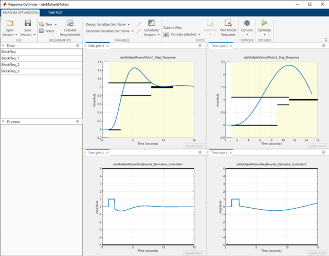
Open the Response Optimizer
In the Simulink model from the Apps tab, click Response Optimizer under Control Systems to launch the Response Optimizer app. With the current settings of the controller variables, observe that neither step response requirement is satisfied.
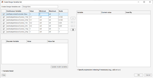
Specify Design Variables
In the Design Variables Set list, select New. The dialog box shows tunable variables. The Slew variable is listed as sdoRateLimitedController:Slew, indicating that the variable is set at the level of the sdoRateLimitedController model. The colon is a delimiter between the model and variable. The Slew variable has the same value for all instances of the controller model. In contrast, the derivative gain for the first controller is listed as sdoMultipleMotors/Control_1:Kd, indicating that the variable is set at the level of the sdoMultipleMotors model, where it appears in the Control_1 block. The forward slash is the delimiter for Simulink blockpaths.
Select the common Slew variable, as well as the Kd, Ki, and Kp parameters for each model. Add these variables to the design variable set. Specify the minimum value for the Slew variable as 0.
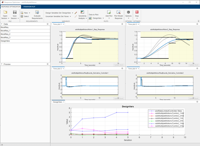
Click OK. A new variable, DesignVars, appears in the Response Optimizer browser. Create a plot of the design variables to see how they evolve during optimization. Under Data to Plot, select DesignVars. Click Add Plot and add an iteration plot. You can use the View tab to arrange the plots so they are all visible.
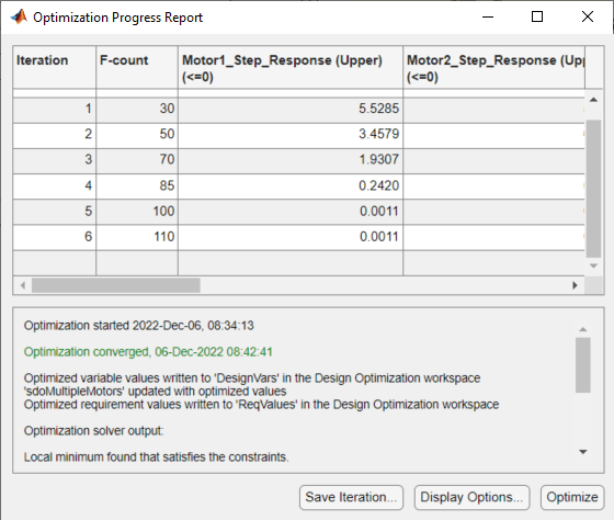
Optimize the Design
To optimize the design, click Optimize. The plots are updated during optimization. When optimization is complete, observe that all design requirements are satisfied. The step responses are within the prescribed bounds, as are the controller output signal derivatives.
Close the models.
bdclose('sdoMultipleMotors')
bdclose('sdoRateLimitedController')