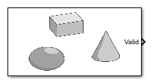
Simulation 3D Actor
Libraries:
Simulink 3D Animation /
Simulation 3D /
Actors
Description
The Simulation 3D Actor block implements an actor in the Unreal Engine® environment. You can use this block to:
Create a movable
sim3d.Actorobject as the root actor and specify actor name.Set how the actor is created and behaves during simulation.
Control actors created using other Simulation 3D Actor block in the 3D environment.
Specify source file to import 3D files for building an appearance for the actor.
Initialize the actor including defining the actor appearance using 3D graphic primitive shapes or mesh data.
Report object interaction events for the actor. By default, the actor enables hit event.
Create and add other
sim3dactor objects to the 3D environment as children of this actor.
Examples
This example shows how to create custom lighting with a point light, a spot light, and a rectangular light using the Simulation 3D Actor block. First, create a room in the 3D environment. Next, create three actors using sim3d.Actor objects, add them as child actors of the room, and position them inside the room. Then, create a point light, a spot light, and a rectangular light, add them as child actors of the room, and position them above the actors inside the room. Finally, in the Simulation 3D Viewer, view the room and its actors illuminated by the different types of light.
Open the model.
open_system("CreateLightUsingSimulink.slx");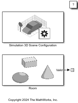
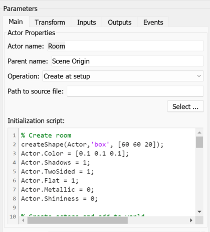
The model includes a Simulation 3D Scene Configuration block and a Simulation 3D Actor block. The Simulation 3D Scene Configuration block implements a 3D simulation environment and sets a view in the scene with the Scene view parameter. The Simulation 3D Actor block, named Room, creates an actor in the 3D environment. The block first creates an empty actor named Room, as specified by the Actor name parameter. The block then runs the Initialization script. In the Initialization script, use Actor as the handle to the actor object created by the Simulation 3D Actor block and World as the handle to the world object created by the Simulation 3D Scene Configuration block. The script builds a box shape for Actor using the createShape function to create a room in the 3D environment and set the properties of the room to visualize the custom lighting. The Initialization script then creates three actors using sim3d.Actor objects with box, sphere, and cone shapes. Set the translation of the actors to position them inside the room. Add the actors to World as child actors of Actor. The Initialization script finally creates a point light, spot light, and rectangular light using the sim3d.Light objects, positions the lights above the actors inside the room, and adds them to World as child actors of Actor. Transform properties of an actor are relative to its parent actor. Set the properties of the child actors for enhanced lighting effects.
Simulate the model and view the custom lighting in the Simulation 3D Viewer. You can visualize the reflections of each light type on the wall behind the actors.
sim("CreateLightUsingSimulink.slx");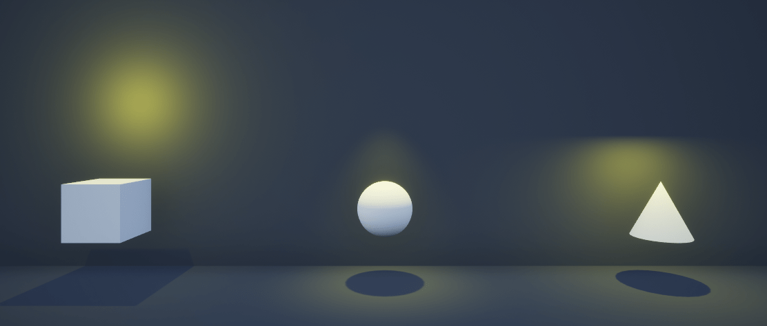
close_system("CreateLightUsingSimulink.slx");Create arrows and text labels in the 3D environment and attach them to an actor using Simulation 3D Actor block.
Open the model.
open_system("CreateAnnotationsUsingSimulink.slx");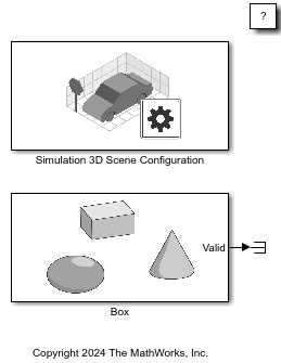
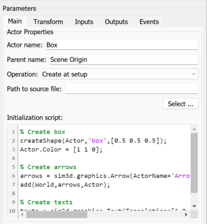
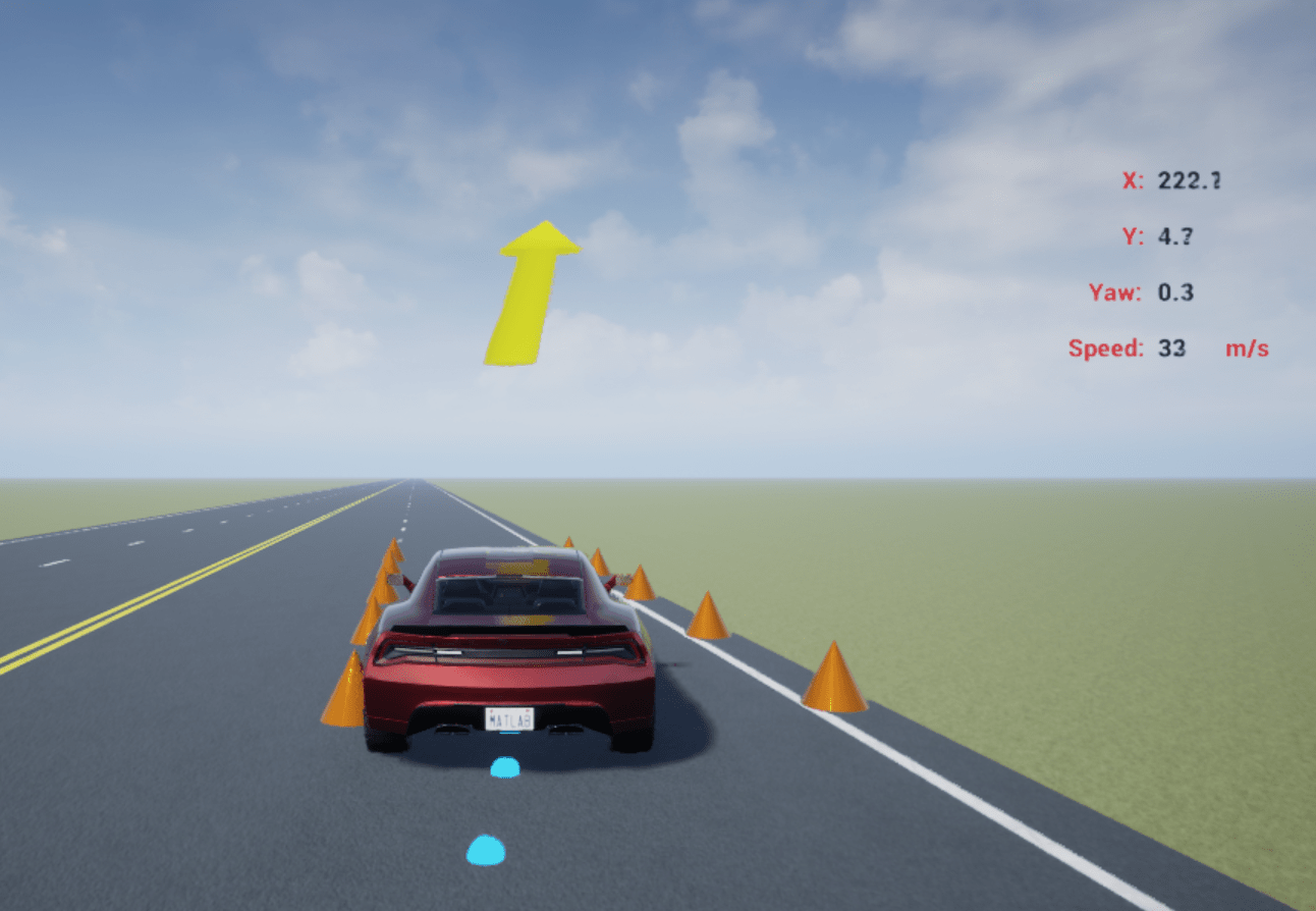
The model includes Simulation 3D Scene Configuration and Simulation 3D Actor blocks. The Simulation 3D Scene Configuration block implements a 3D simulation environment and sets a view in the scene that you specify with the Scene view parameter. The Simulation 3D Actor block named Box creates a box actor in the 3D environment. The block creates an empty actor with the name you specify in the Actor name parameter. Then, the block runs the Initialization script. In the Initialization script, use Actor as the handle to the actor object created by the Simulation 3D Actor block and World as the handle to the world object created by the Simulation 3D Scene Configuration block. The Initialization script builds a box shape for the Actor object using the createShape function. The Initialization script then creates arrows and text labels as child actors of the Actor object using the sim3d.graphics.Arrow and sim3d.graphics.Text objects, respectively. Set the properties of the box, arrows, and text labels. Transform properties of the child actors are relative to the parent actor.
Simulate the model and view the annotated box actor in the Simulation 3D Viewer.
sim("CreateAnnotationsUsingSimulink.slx");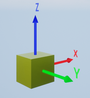
close_system("CreateAnnotationsUsingSimulink.slx");This example shows how to create actors and dynamically control them using the operation modes of Simulation 3D Actor block. You can create actors during simulation and control existing actors by name or instance number.
Use the Operation parameter of the Simulation 3D Actor block to set the block behavior to one of these options:
Create at setup– Create actors before the simulation starts.Create at step– Create actors dynamically during simulation.Reference by name– Control an actor using its name.Reference by instance number– Control an actor using its instance number.
For more details, see Operating Modes.
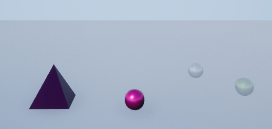
In this example, you create a 3D environment with a plane and pyramid. Then, you create ball actors dynamically during simulation. You also control the properties of the pyramid and ball actors using their names and instance numbers.
Open Model
Open the Simulink model.
open_system("OperationModesOfActorBlock");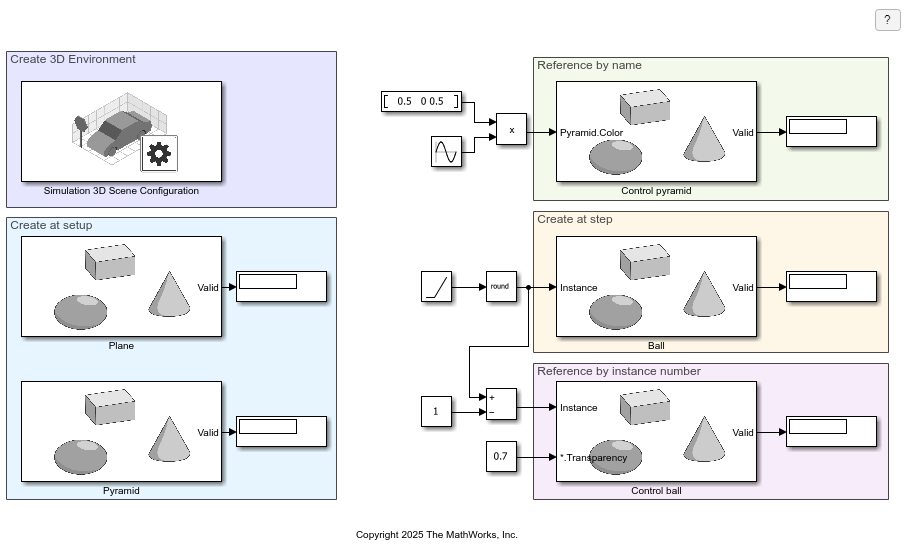
Explore Model
The model includes Simulation 3D Scene Configuration block and Simulation 3D Actor blocks. You must include the configuration block when building Simulink models with Simulation 3D Actor blocks.
Each Simulation 3D Actor block connects its Valid output port to a display, which shows whether the specified actor exists in the 3D environment. The display shows 1 if the actor is present and 0 if it is not.
The model includes these areas:
Create 3D Environment —This area includes a Simulation 3D Scene Configuration block to create the 3D environment. You can configure the view of the 3D environment or define a custom viewpoint using the Simulation 3D Scene Configuration block.
Create at setup —This area includes two Simulation 3D Actor blocks with the Operation parameter set toCreate at setup. During setup, the Simulation 3D Actor block namedPlanecreates a plane actor and the block namedPyramidcreates a pyramid actor in the 3D environment.
Reference by name —This area includes a Simulation 3D Actor block namedControl pyramid, with the Operation parameter set toReference by name. The block uses the actor name specified in the Actor name parameter to identify the pyramid actor in the 3D environment and control its color.
Create at step —This area includes a Simulation 3D Actor block namedBall, with the Operation parameter set toCreate at step. This setting creates a input port Instance. The block generates actors during simulation based on the value at the Instance port. Use a Ramp block and a Round block to generate the integer instance value. When the Instance value is positive, the block creates an actor named 'Actor name + Instance value'.
Reference by instance number —This area includes a Simulation 3D Actor block namedControl Ball, with the Operation parameter set toReference by instance number. This setting creates the input portInstance. Based on the value at theInstanceport, the block looks for the actor with the name 'Actor name + Instance value' in the environment and controls itsTransparencyproperty.
Simulate Model
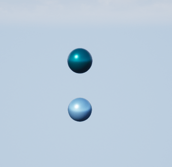
Simulate the model and, in the Simulation 3D Viewer, view the pyramid actor created at the start of the simulation along with the plane actor and the ball actors created during the simulation.
sim("OperationModesOfActorBlock");You can see the pyramid changes color and the ball actors changes its transparency.
Close Model
Close the Simulink model.
close_system("OperationModesOfActorBlock");This example shows how to report actor events in the Unreal Engine® simulation environment using Simulink®. Use the HitEventEnabled, OverlapEventEnabled, and Collisions properties of the actor object to report hit and overlap events. Click event is enabled by default.
First, create a 3D environment. Then, build box actors and set the properties of actor objects to simulate the actors and report events. Then, enable event ports to display the events. Finally, create annotation actors to indicate the start of click event and view the animation in the Simulation 3D Viewer window.
You can detect these actor events:
Hit event
Begin overlap event
End overlap event
Click event
Unreal Engine® uses the physics engine to control actor motion and perform real-time physics calculations when the physics property of an actor is enabled.
Open Model
Open the model.
open_system("ReportEvents.slx");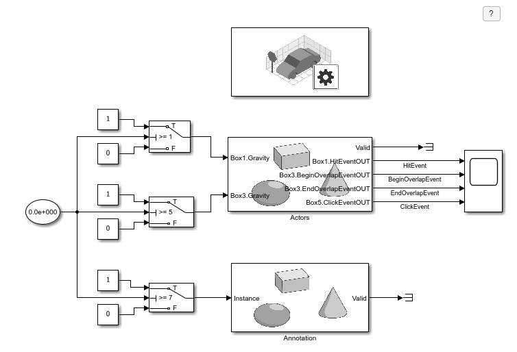
Explore Model Components
The model includes a Simulation 3D Scene Configuration block and Simulation 3D Actor blocks to create a 3D environment with actors. The Simulation 3D Scene Configuration block implements the 3D environment. Double-click the Simulation 3D Scene Configuration block to open the Block Parameters dialog box and set a custom viewpoint.
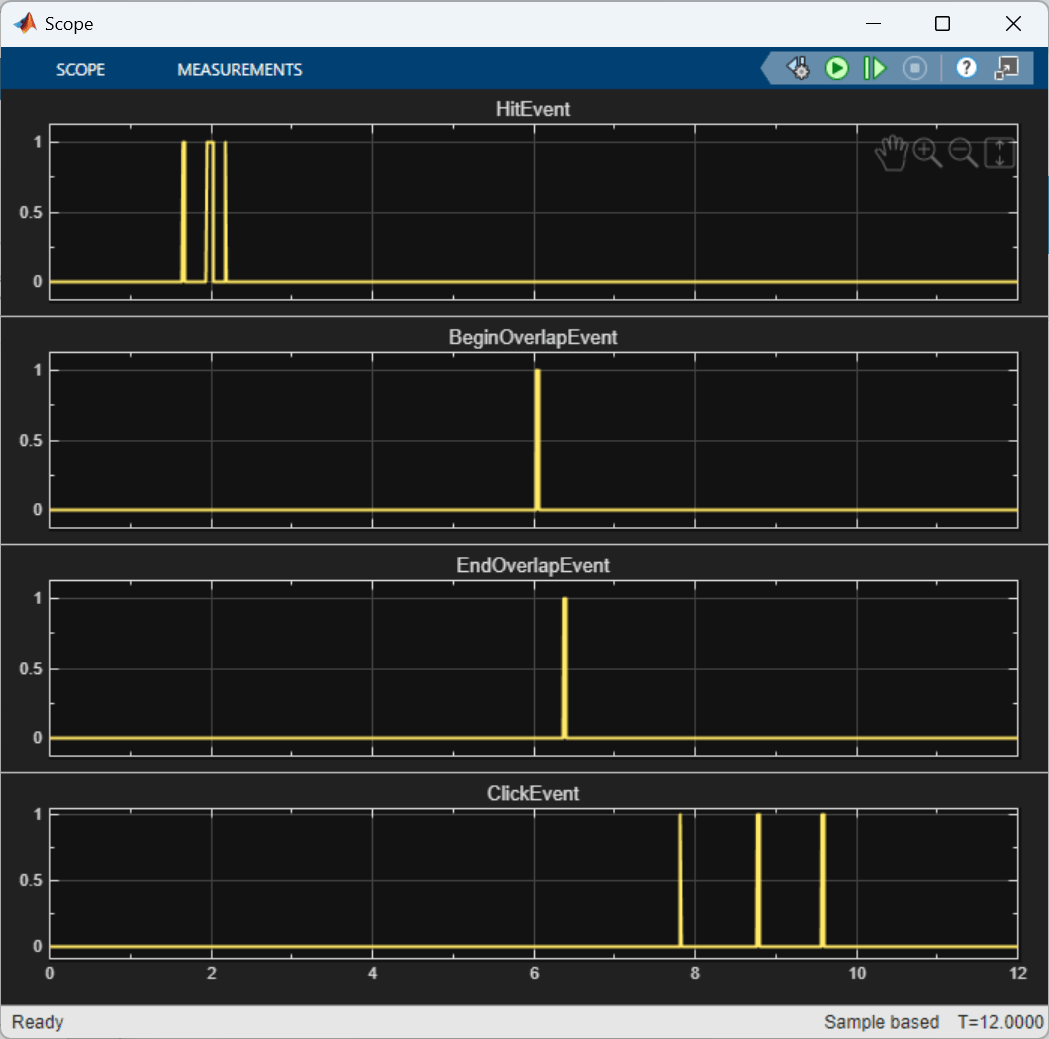
The Simulation 3D Actor block named Actors creates five box actors to report the hit event, overlap event, and click event. For this example, use Clock and Switch blocks to enable gravity for box actors to simulate and report the hit event and overlap event one after the other. Use the Inputs tab of the Simulation 3D Actor block to enable the input ports Box1.Gravity and Box3.Gravity to set the gravity of box actors during simulation. Use the Events tab of the Simulation 3D Actor block to enable the output ports Box1.HitEventOUT, Box3.BeginOverlapEventOUT, Box3.EndOverlapEventOUT, and Box5.ClickEventOUT, and display the events using a Scope block. You can also enable event ports to access the actor properties listed in the Event Attributes. You can use a To Workspace block to store the name or identifier of the actor that participates in an event.
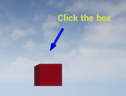
The Simulation 3D Actor block named Annotation creates annotation actors using the sim3d.graphics.Text and sim3d.graphics.Arrow objects to visualize the click event. The text label displays Click the box, and an arrow points to the box actor to visualize the click event.
Simulate Model
Simulate the model. The Simulation 3D Viewer Window displays five box actors. During simulation, the actors named Box1 and Box2 display the hit event. After the hit event, Box3 starts to overlap Box4. The Simulation 3D Viewer displays Click the box and an arrow points at Box5. To report the click event, click Box5. You can also view the reported events in the Scope block.
sim("ReportEvents.slx");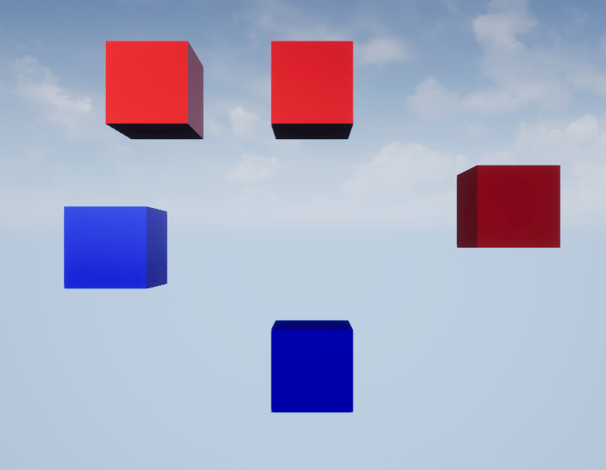
Close Model
Close the Simulink model.
close_system("ReportEvents.slx");Extended Examples

Simulate a Quadcopter
Use Simulation 3D Actor block to simulate a quadcopter.

Create Multiple Instances of Actors
Use For Each Subsystem block to create multiple instances of an actor.
Delete Actor During Simulation Using Simulink
Remove an actor during simulation from the Unreal Engine visualization environment using Simulink®.
Annotate Vehicle Simulation
Use Simulation 3D Actor block to create and add annotations to the 3D environment.
Ports
Input
Output
Parameters
More About
Use the Simulation 3D Actor block to control simulation during runtime by modifying the block ports. To control actors during simulation, you can use the Inputs tab of the block mask to add input ports to the block which can then be used to control specific actors.
Similarly, you can use the output and event ports of the block mask to get data about the actors from Unreal Engine. The output ports can be modified from the Outputs and Event tabs in the dialog box. Selecting event ports on the Event tab creates corresponding output ports on the block.
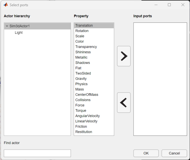
The Browse buttons in Inputs,
Outputs, and Events text area opens up
the port selection app, which you can use to add or delete input and output ports.
Select the actor from the Actor hierarchy to display its
corresponding ports. Although ports can be modified manually, the suggested method
is to use the port selection app.
This table provides the possible input, output, and event Properties of the sim3d.Actor.
| Type | Properties |
|---|---|
| Input and output properties | |
| Event properties |
|
Additionally, these are the possible input and output ports of the
Simulation 3D Actor block if you add sim3d actor objects.
Actors can be controlled for all operating modes, except Create at
step. For all other operating modes, these are some special considerations.
Create at setup– The port selection app in this mode lists the entire tree hierarchy of actors created in the actor block, and you can use the block ports to control the simulation of the parent as well as child actors. These actors are present throughout the entire simulation, and the outputs of the blocks are always valid.Reference by name– In this operating mode, the block can only control a single actor during the simulation, specified using the actor name. If the actor is not present in the world, the block inputs are ignored, the Valid output isfalse, and the remaining outputs are default values (invalid).Reference by instance number– In this operating mode, the Simulation 3D Actor block only controls one actor per time step. In different time steps the block can control different actor based on the value of the Instance input. The port selection app for this operating mode uses*as a placeholder for the actor name. The actor being controlled has the name as a concatenated string: actor name (in block dialog box) + current instance input value. The*wildcard only applies to theReference by instance numberoperating mode. Similar toReference by nameoperating mode, the Valid output isfalsewhenever the actor currently being referenced is not present in the world.
Version History
Introduced in R2022bSee Also
Blocks
- For Each Subsystem (Simulink) | Simulation 3D Scene Configuration
Classes
Topics
- Create 3D Simulation Using Simulink
- Create 3D Simulations in Unreal Engine Environment
- Simulate Actor with Kinematics Properties Using Simulink
- Interact with Unreal Engine Simulation Environment
- How 3D Simulation in Unreal Engine Environment Works
- Unreal Engine Simulation Environment Requirements and Limitations
- Generate Skidpad Test (Vehicle Dynamics Blockset)