Import 3D Models from CAD Tools
To import models from CAD tools, convert your product assembly model into the X3D format used by the Simulink® 3D Animation™ software. Most CAD tools have X3D export filters. If the export filter is not directly available in the CAD tool, you can use conversion utilities available from third parties.
When exporting CAD models into the X3D format, you can set several options to customize the output. You can set options that are specific to the export filters or are general CAD file properties. Consult your CAD system documentation for specific details on how to set these properties. Some of the most typical and useful CAD file properties are:
Level of Detail Considerations
Units Used in Exported Files
Coordinate System Used
Assembly Hierarchy
Level of Detail Considerations
Usually CAD models are parametric models that use proprietary object rendering methods
to handle various contexts. During model export, the internal parametric model of the
assembly is tessellated. In this process, the model surface is divided into triangular
meshes, represented by the IndexedFaceSet nodes. Before tesselation, set
the granularity of the mesh so that it is suitable for further use. Modifying the polygon
count later is not practical. The resolution independent information of the object shape and
structure is lost and cannot be reconstructed based on the tessellated model.
For effective rendering of moving parts, keep virtual world models as simple as possible, with minimal visible model degradation. Find the appropriate compromise between these two requirements.
Computers and graphic accelerators have a range of performance levels, so there is no firm recommendation for the number of polygons or triangles suitable for use. To assess the complexity of a model, you can display the resulting virtual world 3D file in the Simulink 3D Animation viewer and observe the viewer response to navigation. If you can navigate the virtual world without any significant delays, the model is suitable for further work. If you connect the virtual world to a Simulink model, you have access to more precise measures of suitability. For example, you can find the number of frames rendered per second during simulation.
Units Used in Exported Files
X3D length units are in meters. To scale exported parts correctly in the virtual world, export the parts using meters. If the exported objects are small or large, consider creating your virtual world in some other scale. In this case, export the objects using units other than meters.
Virtual reality viewers measure using dimensions that are comparable to the dimensions
of people, to achieve the immersion effect of virtual reality. Viewers assume that you
prepared the scene so that it can be walked through or examined by a virtual visitor to the
scene (an avatar). The physical dimensions of the avatar are used in calculations for
purposes like collision detection, near-object clipping, or terrain following. To customize
avatar dimensions and other navigation-specific parameters such as default navigation
speed), use the NavigationInfo node. The Simulink
3D Animation viewer enables effective navigation in the virtual world, including scaled
scenes. For example, you can use the viewer to inspect miniature objects or to visualize a
large-scale aircraft operation in space.
Coordinate System Used
X3D uses a Cartesian coordinate system with axes defined so that:
+x points right
+y points up
+z points out of the screen
To avoid transforming object axes into the virtual world system later on, whenever possible, export CAD models using an identical coordinate system. If your CAD tool uses a different coordinate system and does not allow you to change it for the exported objects, note the system differences. Then implement axes transformations in your model later.
For example, if you export a vehicle model so that it points towards the +x axis on a road in the virtual world:
Make the road also point towards the +x direction.
Use the x coordinate for the model of vehicle dynamics.
Make a note of the orientation of the parts in the coordinate system.
When the CAD tool allows you to animate parts and assemblies, reset their positions to the initial state before the export.
Assembly Hierarchy
The export of assembly of parts varies based on the structure of the model, which usually comes in two forms:
All parts are independent from each other, or objects in the scene are independent from each other at the same level of the scene hierarchy. The exported virtual world 3D file has a flat structure, with all part coordinates defined in global coordinates.
Parts follow a hierarchy defined in the CAD tool. The exported virtual world 3D file uses this hierarchy via the
Transform-childrenmechanism, to create a nested structure. In this case, usually part coordinates are defined in the local coordinate system of the parent of the part.For example, you can export a robot with the following object hierarchy. The coordinates of each part are defined in the local coordinate system of the parent:
rotating support — arm — wrist — hand — tool
When the rotating support moves, all other parts are designed to move with it.
The hierarchy of the virtual world 3D file must correspond to the coordinates used in the dynamic model of the assembly as follows:
If all parts in the Simulink or Simscape™ Multibody™ model are defined in global coordinates, use a flat virtual world structure.
If all parts in the Simulink or Simscape Multibody model follow hierarchical relationships, use a nested virtual world structure.
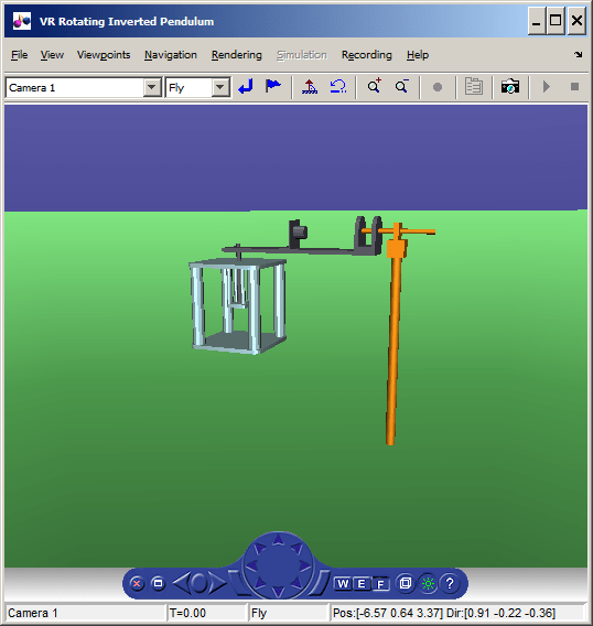
To illustrate these two cases, imagine a rotating pendulum. As the gray arm rotates about the vertical axis, the orange pendulum swings about the z axis in local coordinates of the rotating gray arm.
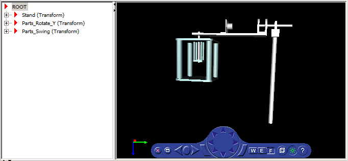
If the pendulum dynamics model uses global coordinates for all moving parts, the virtual world model has a flat structure.
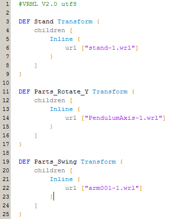
Here is the code for the flat structure.
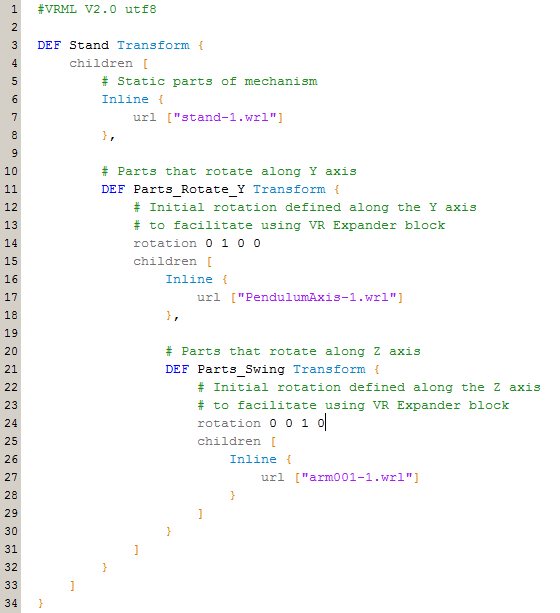
If the pendulum dynamics model uses local coordinates for moving parts, the corresponding virtual world model has a nested structure.
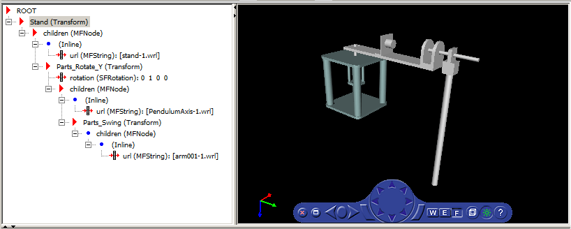
Here is the code for the nested structure.
Some third-party tools allow you to export each part of the assembly into separate
virtual world 3D files. All parts are then referenced in one main file using the
Inline mechanism. Referencing in this manner is the recommended way to
work with assemblies, as the main file is small and easy to understand and modify.
See Also
Functions
Related Topics
Select a Web Site
Choose a web site to get translated content where available and see local events and offers. Based on your location, we recommend that you select: United States.
You can also select a web site from the following list
Americas
- América Latina (Español)
- Canada (English)
- United States (English)
Europe
- Belgium (English)
- Denmark (English)
- Deutschland (Deutsch)
- España (Español)
- Finland (English)
- France (Français)
- Ireland (English)
- Italia (Italiano)
- Luxembourg (English)
- Netherlands (English)
- Norway (English)
- Österreich (Deutsch)
- Portugal (English)
- Sweden (English)
- Switzerland
- United Kingdom (English)
Asia Pacific
- Australia (English)
- India (English)
- New Zealand (English)
- 中国
- 日本Japanese (日本語)
- 한국Korean (한국어)