Run Iterative Simulations Without Recompiling Model for Variant Systems Using Fast Restart
This example shows how to run iterative simulations on a fog lamp controller system using fast restart. The fog lamp controller system can operate in Driver Switch mode or in Sensor Connected mode. In Driver Switch mode, the driver controls the intensity of the fog lamps. In Sensor Connected mode, a sensor adjusts the intensity of the fog lamps based on the intensity of ambient light in the external environment.
When you run iterative simulations on the fog lamp controller system with fast restart enabled, Simulink does not need to recompile the model each time you simulate the model. Using fast restart, you compile a model only once. You can then change the control modes or type of fog lamps and simulate the model again without recompiling the model. For more information on fast restart, see How Fast Restart Improves Iterative Simulations.
Model
Consider the model slexVariantsWithStartup.
The Variant Subsystem block named Controller represents the structural variation. The variant parameter lightVolt represents the parameter variation in the model.
The Controller subsystem enables you to switch between Sensors Connected and Driver Switch modes by using the variant control variable CTRL_MODE. Sensors Connected mode is a sensor-based mode that automatically adjusts the intensity of fog lamps based on the sensor voltage for the varying intensity of ambient light. The Drivers Switch mode represents driver manually switching the fog lamps on and off.
The lightVolt parameter contains fog lamp intensities for different types of fog lamps, LIGHT_TYPE, in Sensor Connected mode. The fog lamp intensities are mapped to the sensor voltage using the 1-D Lookup Table block.
In this example, the variables CTRL_MODE, LIGHT_TYPE, and lightVolt are defined in the PreLoadFcn callback. To view or modify the value of these variables, on the Modeling tab, select Model Settings > Model Properties. On the Callbacks tab, in the Model callback pane, select PreLoadFcn.
To run iterative simulations using fast restart, the activation time of the Controller block and lightVolt is set to startup.
Explore Model Inputs and Outputs
The Signal Editor block generates two signal groups Sensor and Driver that are provided as inputs to the Controller subsystem block.
In the
Sensorsignal group, the x-axis represents time in seconds. The y-axis represents the sensor voltages for varying ambient light intensities in external environment.
In the
Driversignal group, the x-axis represents time in seconds. The y-axis represents the driver action.1indicates that the driver has turned on the fog lamps and0indicates that the driver has turned off the fog lamps.
In this example, the driver turns on the fog lamps for first two seconds. During this time, the output is a delayed driver switch signal. From two seconds onward, the sensor generates voltages based on the intensity of the ambient light. The sensor voltage is then provided as an input to the 1-D Lookup Table block in the Sensor Connected mode. The lookup table then maps the sensor voltages to the fog lamp intensities in lightVolt. lightVolt has multiple values of fog lamp intensities that vary for different types of fog lamps, which are represented by LIGHT_TYPE.

The Scope block outputs these parameter values. The time axis is in seconds.
LightCommand: In the Driver Switch mode,LightCommandis a delayed driver switch signal. TheLightCommandsignal is high if the Driver signal is high, andLightCommandis low if the Driver signal is low. In other words, when the driver turns on the fog lamps, the fog lamps are illuminated. When the driver turns off the fog lamps, the fog lamps turn dim.
In the Sensor Connected mode, LightCommand is same as SensorOutput, provided the sensor is working. LightCommand is high if SensorOutput output is high, and LightCommand is low if SensorOutput is low. LightCommand is independent of the Driver signal. However, LightCommand honors the Driver signal if the sensor is faulty.
Driver:0indicates that the driver has turned off the fog lamps.1indicates that the driver has turned on the fog lamps.
SensorFault: A sensor voltage between0.5and5indicates that the sensor is working correctly and theSensorFaultis0.
SensorOutput: Fog lamp intensities correspond to the sensor voltages specified in the 1-D Lookup Table block.
Iteratively Simulate Fog Lamp Controller System in Driver Switch and Sensor Connected Modes
To simulate the model in Driver Switch mode, perform these settings:
1. To enable fast restart, on the Simulation tab, in the Simulate section, click Fast Restart.
2. In the MATLAB® Command Window, set CTRL_MODE to 2 to activate the Driver Switch mode. Check that the activation time of the Controller subsystem is set to startup.
CTRL_MODE.Value = int32(2);
3. Run the simulation. Use the Scope block to visualize the results.
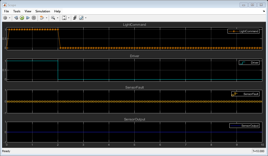
In the Driver Switch mode, the fog lamps are turned on and off based on the action performed by the driver. So, the LightCommand is high when the Driver signal is high and the LightCommand is low when the Driver signal is low. The sensors are not active in this mode and hence the value of SensorFault and SensorOutput is 0. For more information, see Model Inputs and Outputs.
sim('slexVariantsWithStartup');
open_system('slexVariantsWithStartup/Scope')
4. Now, simulate the model in Sensor Connected mode by changing the value of CTRL_MODE to 1. The type of fog lamp, LIGHT_TYPE, is set to LightType.Type1.
CTRL_MODE.Value = int32(1);
5. Run the simulation again. Because fast restart is enabled, Simulink skips compilation and directly starts simulating the model. With fast restart enabled, recompiling is not required for accurate results when there is no structural change in the model. Use the Scope block to visualize the results.
LightCommand is high until SensorOutput is high and is independent of the Driver signal. For more information, see Model Inputs and Outputs.
sim('slexVariantsWithStartup');
open_system('slexVariantsWithStartup/Scope')
Iteratively Simulate Fog Lamp Controller System with Varying Ambient Light in Sensor Connected Mode
1. To enable fast restart, on the Simulation tab, in the Simulate section, click Fast Restart.
2. In the MATLAB Command Window, set CTRL_MODE to 1 to activate the Sensors Connected mode and set the value of LIGHT_TYPE to LightType.Type1.
Check that the activation time of lightVolt is set to startup.
CTRL_MODE.Value = int32(1);
LIGHT_TYPE.Value = LightType.Type1;
3. Run the simulation. Use the Scope block to visualize the results.
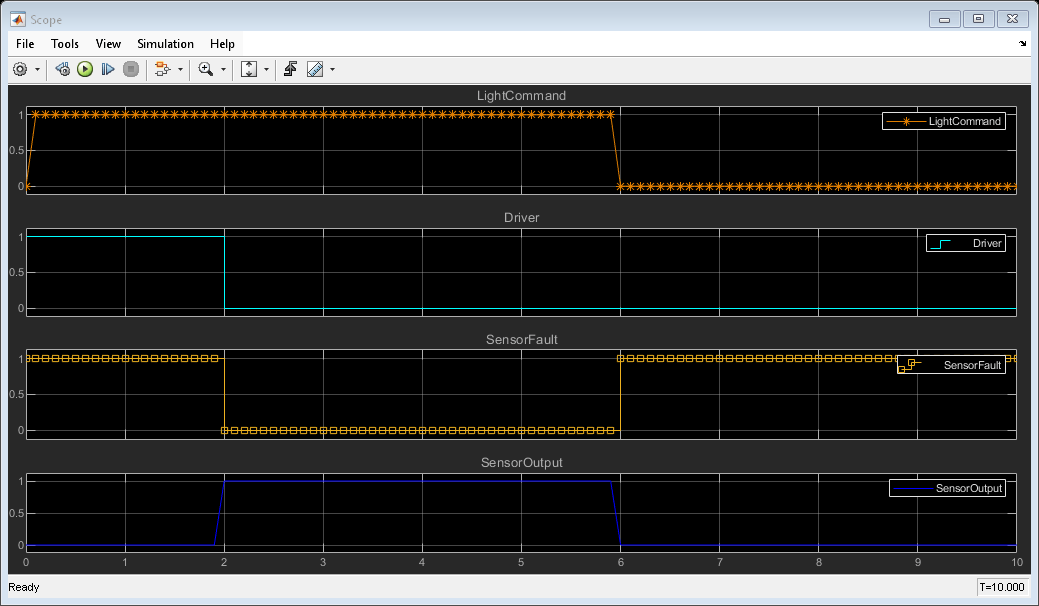
For the first two seconds, the Driver signal from the Signal Editor block is high, so the LightCommand signal is also high. From two seconds onward, the sensor is working and generates SensorOutput based on the sensor voltages from the Signal Editor block. LightCommand is high until SensorOutput is high and is independent of the Driver signal. For information on how sensor voltages are mapped to SensorOutput, see Model Inputs and Outputs.
sim('slexVariantsWithStartup');
open_system('slexVariantsWithStartup/Scope')

4. Change the value of LIGHT_TYPE to LightType.Type2 and run the simulation again. Because fast restart is enabled, Simulink skips compilation and immediately starts simulating the model. Recompiling is not required for accurate results when no structural changes occur in the model.
LIGHT_TYPE.Value = LightType.Type2;
Use the Scope block to visualize the results. For more information, see Model Inputs and Outputs.
sim('slexVariantsWithStartup');
open_system('slexVariantsWithStartup/Scope')

See Also
Improve Code Readability of Variant Parameters Using Enumerated Types
You can also select a web site from the following list:
Americas
- América Latina (Español)
- Canada (English)
- United States (English)
Europe
- Belgium (English)
- Denmark (English)
- Deutschland (Deutsch)
- España (Español)
- Finland (English)
- France (Français)
- Ireland (English)
- Italia (Italiano)
- Luxembourg (English)
- Netherlands (English)
- Norway (English)
- Österreich (Deutsch)
- Portugal (English)
- Sweden (English)
- Switzerland
- United Kingdom (English)