Create Model That Performs Neighborhood Processing
This example shows how to create a model that performs neighborhood processing by using the Neighborhood Processing Subsystem block to blur an image. Neighborhood processing algorithms operate on images by iteratively processing windows of pixels, called neighborhoods, within the image.
Import Image and Output Results
The Neighborhood Processing Subsystem block operates on image data. You can use Computer Vision Toolbox™ blocks to import image data and render images.
Create a model that contains a Neighborhood Processing Subsystem block.
To import an image, add the Image From File (Computer Vision Toolbox) block to your model. Double-click the block to open the block dialog. To prevent precision loss, in the Data Types tab, set the Output data type block parameter to
double.Connect the output port of the Image From File block to the input port of the Neighborhood Processing Subsystem block.
To display images, use the Video Viewer (Computer Vision Toolbox) block. Use two Video Viewer blocks to display the image before and after the Neighborhood Processing Subsystem block.

Configure Neighborhood Processing Subsystem
The Neighborhood Processing Subsystem block accepts a matrix as input and produces a matrix as output. Inside the subsystem, build an algorithm that accepts a neighborhood of the input matrix as input and produces a scalar as output. The block handles the processes of iteratively passing each neighborhood and assembling the output scalars into an output matrix.
Open the Neighborhood Processing Subsystem block.
The Neighborhood control block in the subsystem configures the behavior of the subsystem. Open the Neighborhood block parameters.
Set the Neighborhood size parameter to
[5 5
                1]
. The Neighborhood Processing Subsystem block iterates over 5-by-5 windows for each color channel in the input image. A larger window size produces more blur.Set the Stride parameter to
[1 1 1]and the Processing offset parameter to[0 0 0]. The input matrix has three dimensions, so the Stride and Processing offset parameters must each have three elements.Place a Gain block between the Inport and Outport blocks. Set the Gain value to
1/25.Place a Sum of Elements block between the Gain and Outport blocks. The Sum of Elements block converts a matrix to a scalar. By multiplying the 25 elements of the neighborhood by
1/25and summing the values, the subsystem computes the average value of the neighborhood. This creates a blur effect by blending nearby pixels together.
Simulate and View Results
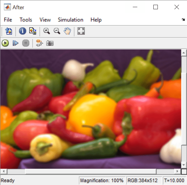
Simulate the model. The processed image is blurry compared to the original image.


See Also
Neighborhood Processing Subsystem
Topics
- Convert RGB Image to Grayscale by Using a Pixel Processing Subsystem Block
- Perform Fog Rectification by Using Neighborhood Processing Subsystem Blocks
- Perform Edge Detection by Using a Neighborhood Processing Subsystem Block
- Perform Corner Detection by Using Neighborhood Processing Subsystem Blocks
- Calculate Optical Flow by Using Neighborhood Processing Subsystem Blocks
- Generate HDL Code from Frame-Based Models by Using Neighborhood Modeling Methods (HDL Coder)
- Use Neighborhood, Reduction, and Iterator Patterns with a Frame-Based Model or Function for HDL Code Generation (HDL Coder)