Monitor Ink Status on Shared Printer Using Simulink Functions
This example shows how multiple clients can send requests to a server and receive a status from the server. Using Simulink® functions, different subsystems can call functions from other subsystems and interact in Simulink and Stateflow®. In this example, you model the ink status monitoring of a shared printer using Simulink functions.
In this example, the clients are three computers and the server is a network printer shared by the computers. You model the computer components as function callers. The computers each generate randomly sized print jobs at regular intervals. The printer interacts with the computers through two Simulink functions on the Simulink canvas and one exported graphical function in Stateflow. You can simulate this example and generate code for the Stateflow chart.
Open the model.
open_system("slexPrinterExample")
The variables in this model are:
job, which represents the number of pages in a print job.work, which represents the total number of pages to print in the queue.ink_status, which is a Boolean value indicating whether there is ink in the printer.ink, which represents how much ink is in the printer. If the value is less than 1, you see a warning. If the value is equal to 0,ink_statusisfalse.
The functions in this model are:
addPrintJobfunction, which randomly generates a print job to queue if theink_statusis greater than 1. To add a print job to the queue, theaddPrintJobfunction callsqueuePrintJob.queuePrintJobfunction, which adds a print job to the queue by updating theworkvariable.printerInk, which updatesinkto represent the printing of a job.
The printer can transition between two states, Idle and Busy. The printer is idle if work is less than or equal to 0, meaning there are no print jobs in the queue. The printer is busy if work is greater than 0, meaning that print jobs are in the queue. When the printer is busy, work updates to decrease the amount of pages in the queue and printerInk is called to update ink_status.
Implement Simulink Function and Function Callers
The computers are client components which use Function Caller blocks to invoke the addPrintJob interface of the printer. The client-server interaction that this function call models can have a negative return value if the printer runs out of ink.

The addPrintJob function is implemented inside of a Simulink Function block. Inside of the Simulink Function is a Function Caller block which invokes queuePrintJob, a Stateflow-exported graphical function.

The queuePrintJob function is implemented inside of a Stateflow chart. In the Stateflow chart, the queuePrintJob interacts with other content in the chart using a local chart variable work.

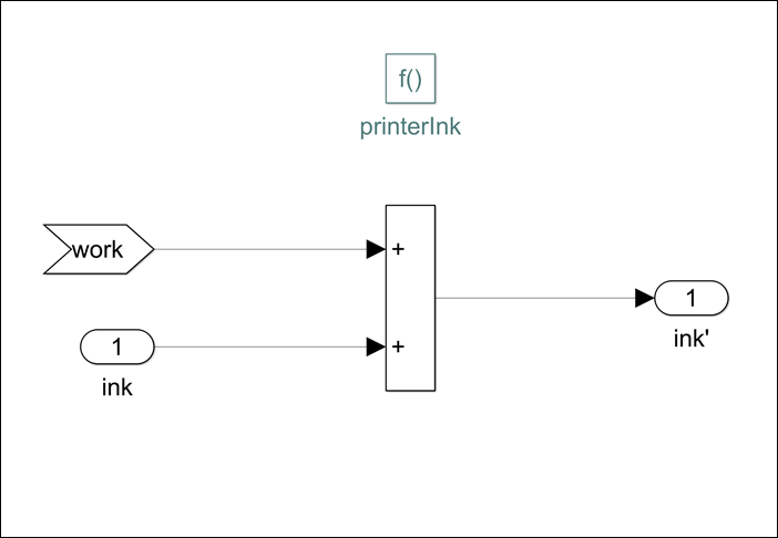
The implementation of the chart makes a call to printerInk, a Simulink function. The printerInk function is implemented in a Simulink Function block which uses the graphical input and outputs to interact with the addPrintJob function.
Display Function Sequences
You can also visualize and debug Simulink functions. To visualize the relation between functions and their respective callers, in the Simulink Editor, on the Debug tab, under Information Overlays, click Connectors. Select Function Connectors from the Connectors pane on the Simulink canvas.
Run the model.
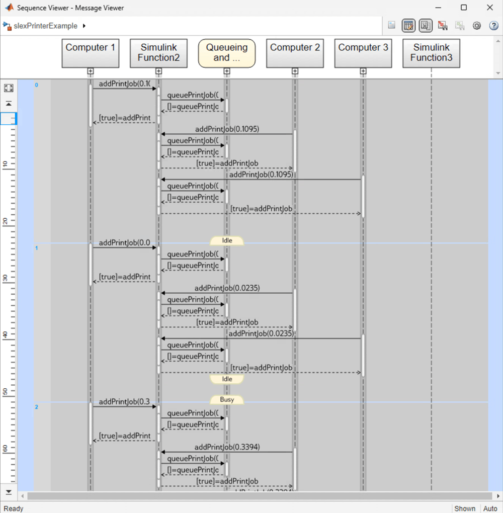
sim("slexPrinterExample");The Sequence Viewer block shows when a computer generates a function call. You can use this information to understand the flow of calls with respect to time and analyze the arguments sent during these calls to functions.
See Also
Simulink Function | Function Caller | Sequence Viewer