Interfacing Angle-Based Rotational and Position-Based Translational Networks
This example demonstrates how to interface angle-based rotational networks with position-based translational networks. The first scenario involves a ball rolling on a slope, utilizing the Wheel and Axle (AB-PB) block. The second scenario shows a camshaft mechanism that uses four Cam and Follower (AB-PB) blocks. Both the Wheel and Axle (AB-PB) and Cam and Follower (AB-PB) blocks have translational and rotational ports, and they include an isometric view of the part rotating on its axis. For the model to function as expected, it is important to align these ports and the isometric view correctly with the respective networks. This example describes how to configure this alignment and discusses other important conventions for using these blocks effectively.
Ball on Slope Example
In this model, a ball is initially stationary on a ramp with a 30-degree slope. The force of gravity causes the ball to roll down the slope. A translational damper between the mass and World block represents air resistance to the ball's motion. The model provides four different physical views of the system, each defining different directions for positive rotation and translation. Correspondingly, it includes four Simscape™ networks configured to match these physical views.
Open the model.
open_system('InterfacingRotationalAndTranslationalRollingBall');
In this scenario, the rotational axis is translating. The rotational domain supports this scenario because all rotational dynamics outside the Wheel and Axle (AB-PB) block rely solely on the Wheel and Axle's rotational motion and torque, not on the translational acceleration of the axis. This behavior possible because all inertias and loads are symmetrically distributed around the axis in this system.
Configure the Physical View
The physical views shown here correspond to the ball's initial state, with an initial angle of 0 degrees. The angle between the red circle and the vertical line in the physical view corresponds to the value of theta for the Inertia and Wheel and Axle blocks in the Simscape schematic. In all of the physical views, the hill slopes downward to the right, causing gravity to make the ball rotate clockwise and move downward to the right as it rolls. The four different systems define the positive translational and rotational directions in various ways. The positive direction of the translational network can point uphill or downhill, while the rotational axis can point either into or out of the canvas. This table summarizes the network positive directions.
System | Positive Translational Direction | Positive Rotational Axis Direction |
1 | Downhill to the right | Clockwise |
2 | Uphill to the left | Clockwise |
3 | Downhill to the right | Counterclockwise |
4 | Uphill to the left | Counterclockwise |
Configure the Translational Network
In all physical views, the hill slopes downward to the right with an angle equal to 30 degrees. In Systems 1 and 3, the positive x-direction in the physical views points downhill to the right. Conversely, in Systems 2 and 4, the positive x-direction points uphill to the left. Blocks in the translational models all move parallel to the hill slope. Due to the relatively shallow slope, all translational networks are shown horizontally on the canvas.
In position-based translational networks, the internal positive direction for two-port blocks ports points from port B to port F. To ensure intuitive interpretation of force and length, it's important to align all blocks in the network so their internal positive directions point towards the same direction. The direction that the two-port blocks point towards represents the translational network's positive direction. The Force Flow in the Position-Based Translational Domain example provides more details on force flow conventions in position-based translational networks.
For Systems 1 and 3, where the positive x-directions point downhill to the right, the corresponding Simscape schematics have the translational network's positive direction also pointing to the right. To be consistent with the translational positive direction pointing to the right, the Mass and Damper blocks both have port F on the right, and the Wheel and Axle block has translational port Ft on the right. For Systems 2 and 4, where the positive x-directions point uphill to the left, the Simscape schematics have the translational network's positive direction pointing to the left.
The Positive direction incline angle parameter in the Translational Mechanical Properties block defines the slope of the translational network's positive direction relative to a horizontal plane, influencing how gravity affects mass. This angle ranges from 0 to 180 degrees when the translational network's positive direction points uphill (indicating gravity induces motion in the negative direction) and from 0 and -180 degrees when the translational network's positive direction points downhill (indicating gravity induces motion in the positive direction). The Positive direction incline angle parameter is independent of any properties in the rotational network. For Systems 1 and 3, the Positive direction incline angle is -30 degrees since the network's positive direction points downward. In contrast, for Systems 2 and 4, the Positive direction incline angle is 30 degrees since the network's positive direction points upward. For further details on gravity effects in the position-based translational domain, refer to the Gravity and Friction in the Position-Based Translational Domain example.
Run the simulation to observe the ball's translational position over time in each system.
open_system('InterfacingRotationalAndTranslationalRollingBall/Ball Position (m)');
sim('InterfacingRotationalAndTranslationalRollingBall');

As expected from the the physical views, Systems 1 and 3 show the ball moving in the positive direction, while Systems 2 and 4 show the ball moving in the negative direction.
Configure the Rotational Network
In all of the systems, the physical view shows the rotational axis of the ball as either pointing into or out of the Simulink® canvas, corresponding to a front view of the axis.
All icons in the angle-based rotational library present a side view of a part on an axis, which is parallel to the axis. Connections between blocks are shown in this side view. In angle-based rotational networks, the internal positive direction of two-port blocks points from port B to port F in the side view. For intuitive torque interpretation, align all blocks in the rotational network to match their internal positive directions. The direction that the two-port blocks point towards represents the rotational network's positive direction.
In the Ball on Slope model, all rotational networks display a horizontal side-view axis pointing from left to right. The rotational ports of the Wheel and Axle block are labeled Br and Fr to distinguish them from the block's translational ports. To align with the rotational network's positive direction, the Wheel and Axle block has port Br on the left. The Wheel and Axle block optionally hides port Fr because this system does not have any rotational blocks connected to the right of it. If port Fr were enabled, it would appear on the right in these networks.
Several block icons in the angle-based rotational library feature an isometric view that includes both an axis side view and a front view. The front view lies in the plane of rotation. You configure the isometric view so that the front view represents either the B port or F port. If the front view represents the F port, the positive axis direction points out of the canvas, and positive rotation is counter-clockwise in the front view, according to the right-hand rule. Conversely, if the front view represents the B port, the positive axis direction points into the canvas, and positive rotation is clockwise in the front view. Configuring the front view facilitates intuitive interpretation of the Wheel and Axle (AB-PB) block behavior.
For Systems 1 and 2, the physical view shows the rotational axis pointing into the page. According to the right-hand rule, the clockwise rolling of the ball results in a positive rotational velocity. The corresponding angle-based rotational network front views also show the axis pointing into the page. The Inertia (AB) and Wheel and Axle (AB-PB) blocks have the Positive axis direction parameter set to Into canvas.
For Systems 3 and 4, the physical view shows the rotational axis pointing out of the page. Using the right-hand rule, the clockwise rolling of the ball results in a negative rotational velocity. The corresponding angle-based rotational network front views also show the axis pointing out of the page. The Inertia (AB) and Wheel and Axle (AB-PB) blocks have the Positive axis direction parameter set to Out of canvas.
Run the simulation to observe the ball's angle versus time in each system.
close_system('InterfacingRotationalAndTranslationalRollingBall/Ball Position (m)');
open_system('InterfacingRotationalAndTranslationalRollingBall/Ball Angle (rad)');
sim('InterfacingRotationalAndTranslationalRollingBall');

As expected from the physical views, Systems 1 and 2 show the ball rotating in the positive direction, while Systems 3 and 4 show the ball rotating in the negative direction.
Configure the Wheel and Axle Block Translational Ports
The Wheel and Axle (AB-PB) block has two key parameters for configuring the translational ports: Translational network positive direction and Translational port for axis (graphical). Adjusting these parameters ensures that the relationship between translational and rotational motion aligns with your system's physical view and allows the block icon to accurately reflect system behavior.
In your physical view, you choose a positive direction for both translational and rotational motion based on your preferences. When configuring your model, you align the rotational and translational networks' positive directions with your physical view. The model lets you adjust these directions independently. Once you have established each network's positive direction, adjust the Wheel and Axle (AB-PB) block's ports for intuitive model interpretation.
The Wheel and Axle (AB-PB) block includes two angle-based rotational ports, labeled Br and Fr, and two position-based translational ports, labeled Bt and Ft. For intuitive modeling, ensure that the direction from Br to Fr aligns with the rotational network's positive axis direction in the side view, and the direction from Bt to Ft aligns with the translational network's positive direction. In some systems, these two directions are the same, while in others, they are opposite. Adjust the Translational network positive direction parameter to correctly position the Bt and Ft ports, reflecting the alignment of the translational and rotational networks.
In Systems 1 and 3, both the rotational and translational network positive directions point to the right. Therefore, set the Translational network positive direction to Same as rotational network side-view positive direction. In Systems 2 and 4, the rotational network's positive direction points to the right, but the translational network's positive direction points to the left. Thus, set the Translational network positive direction to Opposite of rotational network side-view positive direction.
The translational ports Bt and Ft of the Wheel and Axle (AB-PB) block represent the axis's translation and the wheel's instantaneous contact point on the surface. For a stationary surface, this contact point has zero translational velocity. The Translational port for axis (graphical) parameter determines which port represents the contact point and which represents the axis. Adjust this parameter so that the schematic's axis and contact point ports mirror their positions in the physical view, while keeping the Bt and Ft ports aligned with the translational network's positive direction.
In Systems 1 and 3, port Ft connects to the translating mass, so the Translational port for axis (graphical) parameter is set to Port F. In Systems 2 and 4, port Bt connects to the translating mass, so the parameter is set to Port B.
The Wheel and Axle block icon indicates how rotation and translation are related. Consider the axis front view and the translational ports, which represent the wheel's axis and instantaneous contact point on the surface. When the wheel rotates, its axis pivots around the contact point. As the wheel pivots, its radius acts like a lever, moving the wheel axis either to the right or left. This movement corresponds to the positive or negative direction of the translational network on the model canvas. In System 1, when the wheel rotates with positive rotational velocity (clockwise) around the contact point, the central axis moves to the right, which is the positive translational direction. Conversely, in System 3, when the wheel rotates with positive rotational velocity (counterclockwise) around the contact point, the central axis moves to the left, which is the negative translational direction.
Configure the Torque Sensor
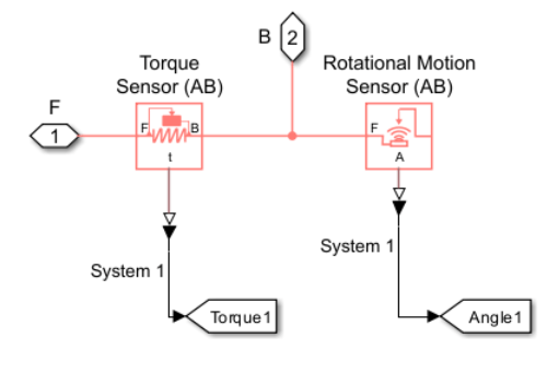
This model employs torque sensors to measure the torque acting on the ball's axis. The torque that initiates the ball's rolling is generated by the force exerted from the surface at the contact point. A Torque Sensor (AB) block is used to measure the torque, with the sensor's port B connected to the Wheel and Axle (AB-PB) rotational port Br and the sensor's port F connected to the Inertia (AB) block. The sensor block measures the torque of the system at port B acting on the system at port F, so this sensor configuration measures the torque of the Wheel and Axle mechanism acting on the ball's inertia.
This image shows the subsystem containing the torque sensor, where port F is connected to the inertia block and port B to the Wheel and Axle block.

View the Rotational Sensor1 subsystem, which contains both a Torque Sensor (AB) and a Rotational Motion Sensor (AB).
open_system('InterfacingRotationalAndTranslationalRollingBall/Rotational Sensor1');
Run the simulation and view the torque acting on the ball axis versus time in each of the systems.
close_system('InterfacingRotationalAndTranslationalRollingBall/Ball Angle (rad)');
open_system('InterfacingRotationalAndTranslationalRollingBall/Torque Acting on Ball Axis (Nm)');
sim('InterfacingRotationalAndTranslationalRollingBall');

In Systems 1 and 2, the physical views indicate that the torque is positive, facilitating positive rotation. Conversely, in Systems 3 and 4, the views show that the torque is negative, resulting in negative rotation. As expected, the initial torque of Systems 1 and 2 is positive while the initial torque of Systems 3 and 4 is negative. Over time, the torque gradually approaches 0 N*m as the ball ceases to accelerate and the gravitational force component parallel to the ramp balances the translational damping force acting on the ball.
Camshaft Example
This model features a camshaft with four cams, each driving a knife-edge follower on a spring.
Open the mode to explore its blocks.
open_system('InterfacingRotationalAndTranslationalCamshaft');
Define the Cam Profile
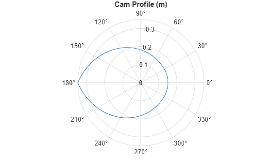
The cam has a constant radius of 0.15 m between -30 to 30 degrees. From 30 to 180 degrees, the radius increases parabolically from 0.15 m at 30 degrees. From 180 to 330 degrees, the radius decreases parabolically back to 0.15 m.
This code defines and plots the cam's radius using polar coordinates.
theta_TLU = 0:1:359; % [deg]

Rmin = 0.15; % Minimum radius [m]
Rmax = 0.35; % Maximum radius [m]
thetaC = 30; %  Radius is constant over [-thetaC, thetaC]

A = (Rmax - Rmin) / (180 - thetaC)^2; % Constant parameter for radius continuity at thetaC

% Initialize the radius vector
R_TLU = zeros(1, length(theta_TLU));

for i = 1:length(theta_TLU)
    if theta_TLU(i)< thetaC
        R_TLU(i) = Rmin;
    elseif theta_TLU(i) < 180
        R_TLU(i) = Rmin + A*(theta_TLU(i) - thetaC)^2;
    elseif theta_TLU(i) < 360 - thetaC
        R_TLU(i) = Rmin + A*(360 - theta_TLU(i) - thetaC)^2;
    else
        R_TLU(i) = Rmin;
    end
end
clear i

figure;
polarplot(deg2rad(theta_TLU), R_TLU);
title('Cam Profile (m)');

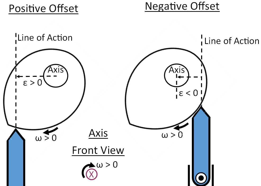
In the Cam and Follower (AB-PB) blocks, the Angle vector and Radius vector parameters define the cam profile. The Offset between follower line of action and axis parameter specifies the perpendicular distance between the cam's axis of rotation and the knife-edge follower translational path. This distance is also known as eccentricity, . A positive Offset between follower line of action and axis indicates that the knife-edge follower's path is shifted in the direction of positive cam rotation. A negative Offset between follower line of action and axis indicates that the knife-edge follower's path is shifted in the direction of negative cam rotation. The cam-followers in this system have 'Offset between follower line of action and axis' equal to -0.01 m. The image below illustrates the relationship of a positive and negative offset with the axis and follower's line of action.

Configure the Cam Offset Angles
The cams are rigidly attached to the shaft at various angles, as shown in the physical view, which illustrates the initial cam angles. The angles are:
Cam-Follower | Initial angle (deg) |
1 | 120 |
2 | 0 |
3 | 180 |
4 | 60 |
A Rotational Initial Spacer (AB) block sets the initial angle of Cam-Follower1 relative to the Rotational World (AB) block. Additionally, Rotational Spacer (AB) blocks between the Cam-Followers define the angular separation between adjacent cams.
Simulate the model to observe the cam angles.
open_system('InterfacingRotationalAndTranslationalCamshaft/Cam Angle (deg)');
sim('InterfacingRotationalAndTranslationalCamshaft');

During the simulation, the cams complete three revolutions. The Rotational Motion Sensors wrap the angle between 0 and 360 degrees, making it easier to visualize each revolution in the scope. The scope results also verify the initial angles of each cam.
Configure the Ports and Orientation
In the physical view, the translational axis, x, is shown pointing upwards from the same reference point where the springs are attached. The Mechanical Translational Properties (PB) block specifies the translational network positive direction is 90 degrees relative to the horizontal. To ensure consistency between the schematic and physical views, the Cam and Follower (AB-PB) blocks have the Rotational axis positive direction set to Into canvas and the Translational port for cam follower (graphical) set to Port B.
Set Boundary Conditions and Variable Initial Targets
Each spring's B node is connected to a Translational World (PB) block, resulting in positions and velocities of 0. Each Cam-Follower's Ft node is connected to the Translational Spacer (PB) block, which specifies a stationary position of 0.5 m.
The model includes these high-priority initial targets:
A Rotational Initial Spacer specifying the angle of Cam-Follower1.
Rotational Spacers specifying the angles of the other three cams.
All masses have an initial velocity of 0 m/s.
All masses experience an initial accelerational force of 0 N, indicating non-acceleration.
A Translational Spacer (PB) length of 0.5 m between the Translational World (PB) and shaft axis, which is represented by node Ft on the Cam-Follower blocks. This spacer ensures a stationary position of 0.5 m for the shaft axis in the translational network.
All translational springs have rest lengths of 0.4 m, ensuring that the springs remain compressed as the translational lengths of the Cam-Followers vary from about 0.15 to 0.35 m within the 0.5 m distance between the stationary Translational World (PB) and shaft axis.
A Rotational Velocity Source (AB) drives the cam at a constant velocity of 1 degree per second.
The Cam-Follower blocks have Model translational compliance between cam and follower prevent overconstraining the mass acceleration.
View the Follower Responses
Simulate the model to view the knife-edge follower positions.
close_system('InterfacingRotationalAndTranslationalCamshaft/Cam Angle (deg)');
open_system('InterfacingRotationalAndTranslationalCamshaft/Follower Position (m)');
sim('InterfacingRotationalAndTranslationalCamshaft');

As expected from the cam profile, the followers undergo a parabolic rise phase, a dwell phase, and a parabolic fall phase, with positions ranging from 0.15 to 0.35 m. These positions correspond to the maximum and minimum cam radii, respectively, as the extending cam length drives the follower in the negative translational direction. The follower positions do not precisely range from 0.15 to 0.35 m due to the offset between the follower's line of action and axis, as well as the cam-follower compliance.
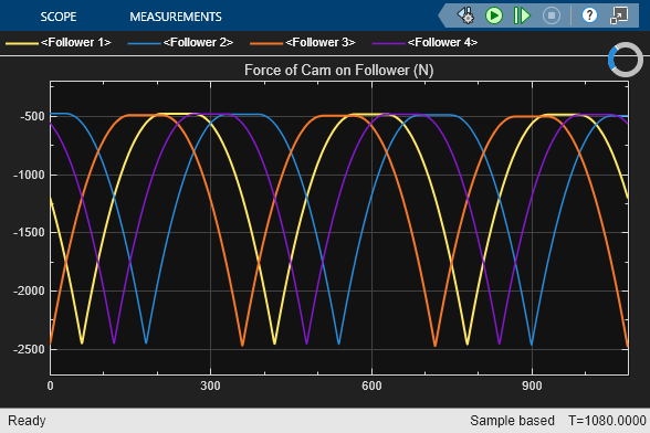
Simulate the model to view the force of the cam on the knife-edge follower.
close_system('InterfacingRotationalAndTranslationalCamshaft/Follower Position (m)');
open_system('InterfacingRotationalAndTranslationalCamshaft/Force of Cam on Follower (N)');
sim('InterfacingRotationalAndTranslationalCamshaft');

As expected due to the preload in the Translational Springs, the force exerted by the cam on the follower is always negative. This negative value indicates that the cam is pushing the follower in the negative translational direction, which is downward in this schematic. The maximum force occurs when the cam's largest radius drives the follower, pushing the follower to its lowest position and compressing the spring to its shortest length. Conversely, the minimum force occurs when the cam has its smallest radius driving the follower.